81
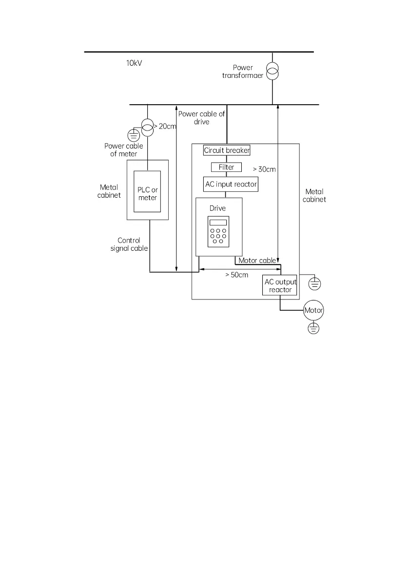
Electrical installation diagram for the drive
Fig. 4-37 Installation diagram for the drive
The grounding cable of the motor shall be grounded at the drive side. The motor and the drive shall be separately
grounded.
The motor cable and control cable should be shielded or armored. The shielding metal mesh shall be connected to both
ends of the grounding cable through cable clamps to avoid the twisting of the ends of the metal mesh. Otherwise, the
shielding effect will be reduced in the high-frequency conditions.
Ensure good conductivity among the mounting plate, mounting screws and the drive’s metal enclosure. The tooth-type
paint scraping gasket and conductive mounting plate shall be used.
If there is any sensitive device on the site, a separate power filter can be installed at the sensitive device side to reduce
the cost.


 To Next Page