CHARGING AND STARTING SYSTEM
90-828631R3 MARCH 1999 Page 2B-15
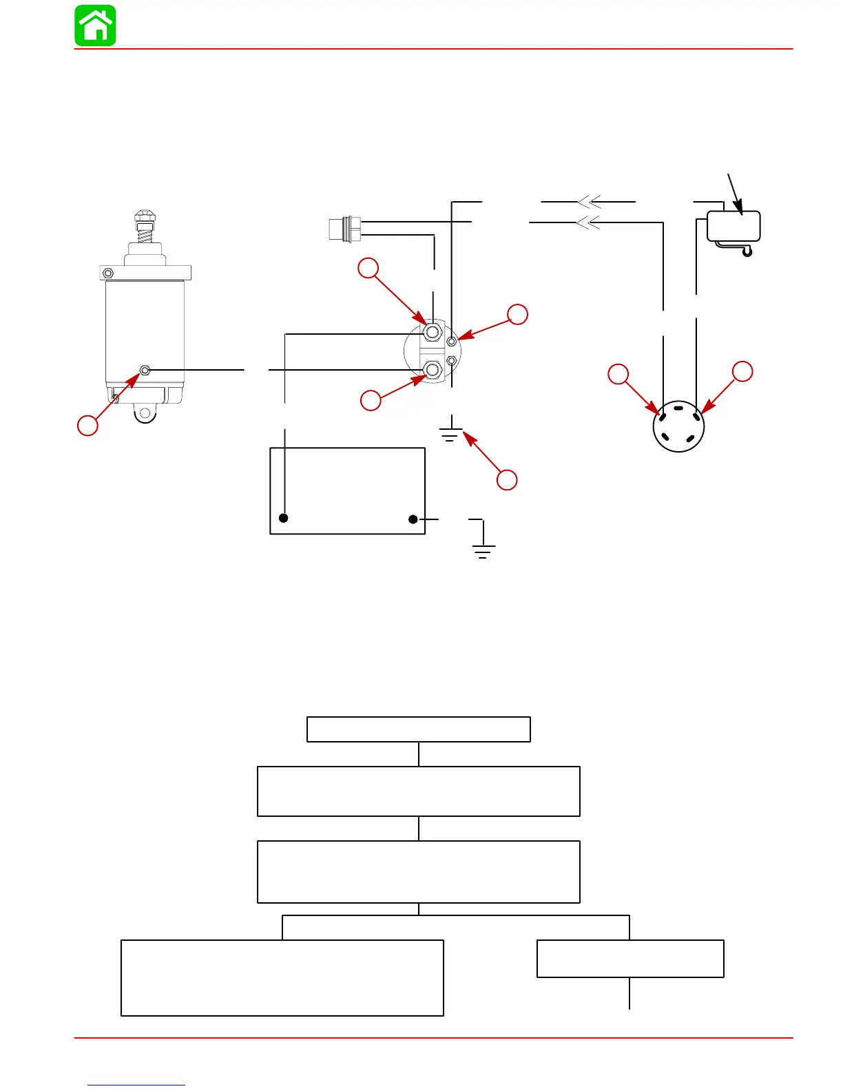
The following “STARTING CIRCUIT TROUBLESHOOTING FLOW CHART” is designed as
an aid to troubleshooting the starting circuit. This flow chart will accurately locate any exist-
ing malfunction. Location of “TEST POINTS” (called out in the chart) are numbered in dia-
gram below.
Starter Motor Does Not Turn
SAFETY WARNING: Disconnect BLACK (starter motor)
cable from starter solenoid test point 1 BEFORE making
tests 1-thru-7 to prevent unexpected engine cranking.
TEST 1
Use an ohmmeter (R x 1 scale) and connect meter leads be-
tween NEGATIVE (-) battery post and common powerhead
ground.
No continuity indicated; there is an open circuit in the BLACK
NEGATIVE (-) battery cable between the NEGATIVE (-) battery
post and the powerhead.
• Check cable for loose or corroded connections.
• Check cable for open.
Continuity Indicated
Proceed to TEST 2, on next page.
Starting Circuit Troubleshooting Flow Chart
+
AB
NEUTRAL START SWITCH
IGNITION SWITCH
STARTER
STARTER
SOLENOID
BATTERY
20 AMP FUSE
–
Blk
Blk = Black
Blu = Blue
Brn = Brown
Gry = Gray
Grn = Green
Orn = Orange
Pnk = Pink
Pur = Purple
Red = Red
Tan = Tan
Wht = White
Yel = Yellow
Yel
Red/ Pur
Red
Red
Yel/ RedYel/ Red
Yel/ Red
Blk
Blk
1
2
3
4
5
6
7

 Loading...