1
2
3
4
5
6
7
8
9
10
11
12
13
14
15
16
17
18
19
20
21
6
10
22
25
95
110
95
25
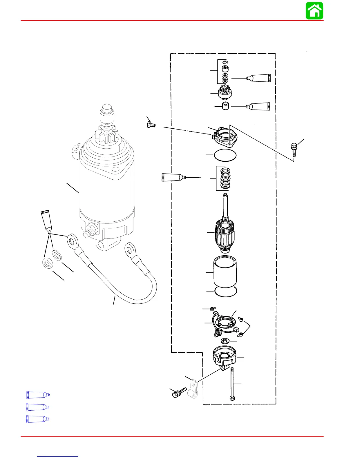
Liquid Neoprene (92-25711--2)
95
2-4-C w/Teflon (92-850736A1)
110
4-Stroke Outboard Oil (92-828000A12)
CHARGING AND STARTING SYSTEM
Page 2B-4 90-828631R3 MARCH 1999
Starter Motor (S/N-0G472132 & Below)

 Loading...