CYLINDER BLOCK/CRANKCASE
Page 4B-1790-828631R3 MARCH 1999
6. Insert a screwdriver at the pry points between the crankcase cover and block to sepa-
rate.
53744
a
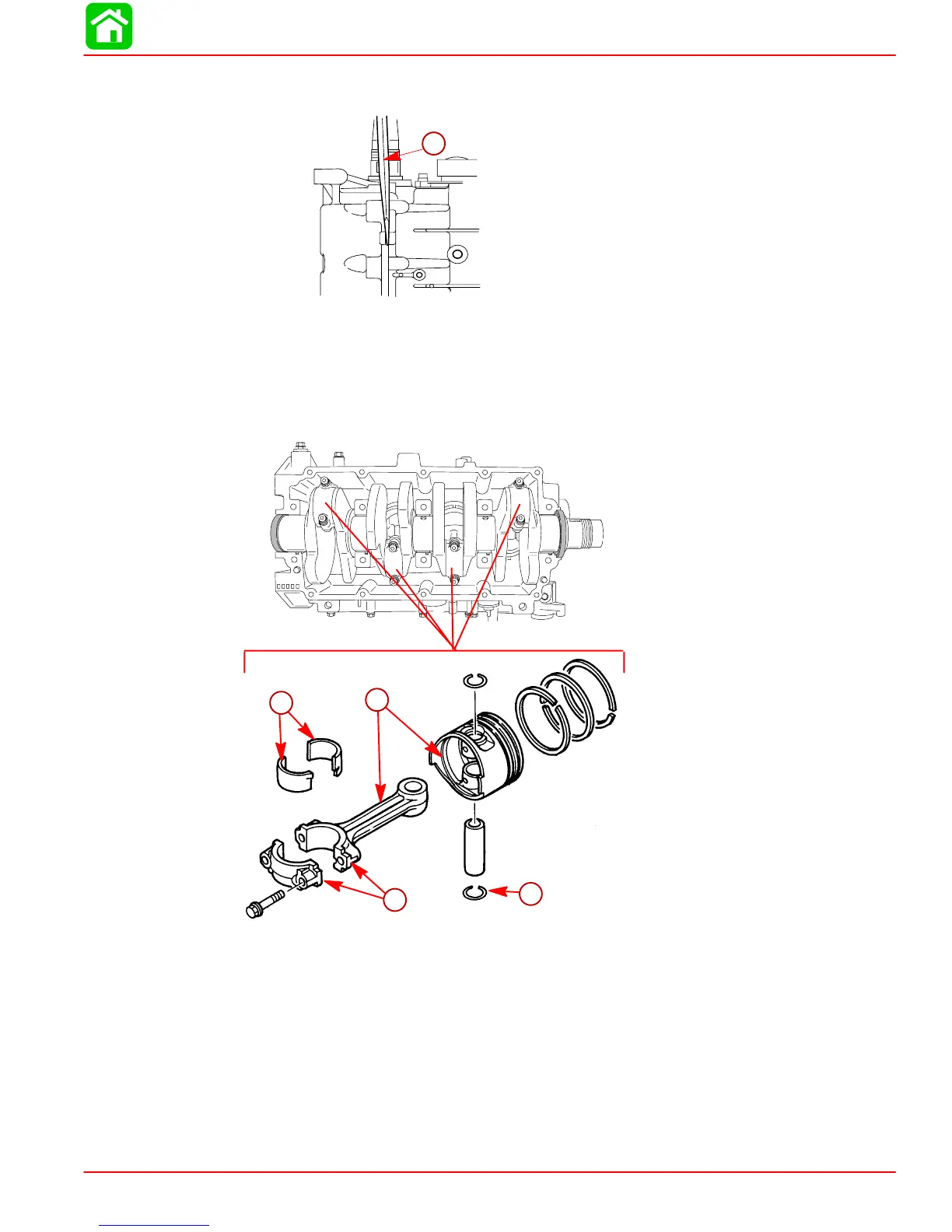
7. Use a 5/16 in. 12 point socket and remove connecting rod bolts.
8. Remove carbon ridge from the cylinder bore using a burr knife. Push out the pistons.
Keep each piston, connecting rod, and cap together as an assembly.
NOTE: Each connecting rod and cap are a matched set. They must not be interchanged.
53824
a
b
d
c
a-Remove Circlips with a Needle Nose Pliers
b-Connecting Rod and Cap are a Matched Set, Don’t Interchange
c-Scribe the Cylinder Number (1 thru 4) on Inside of Each Piston and Connecting
Rod so they can be Reinstalled in their Original Location
d-Connecting Rod Bearings – Do Not Interchange. Reinstall in Original Locations

 Loading...