CHARGING AND STARTING SYSTEM
Page 2B-12 90-828631R3 MARCH 1999
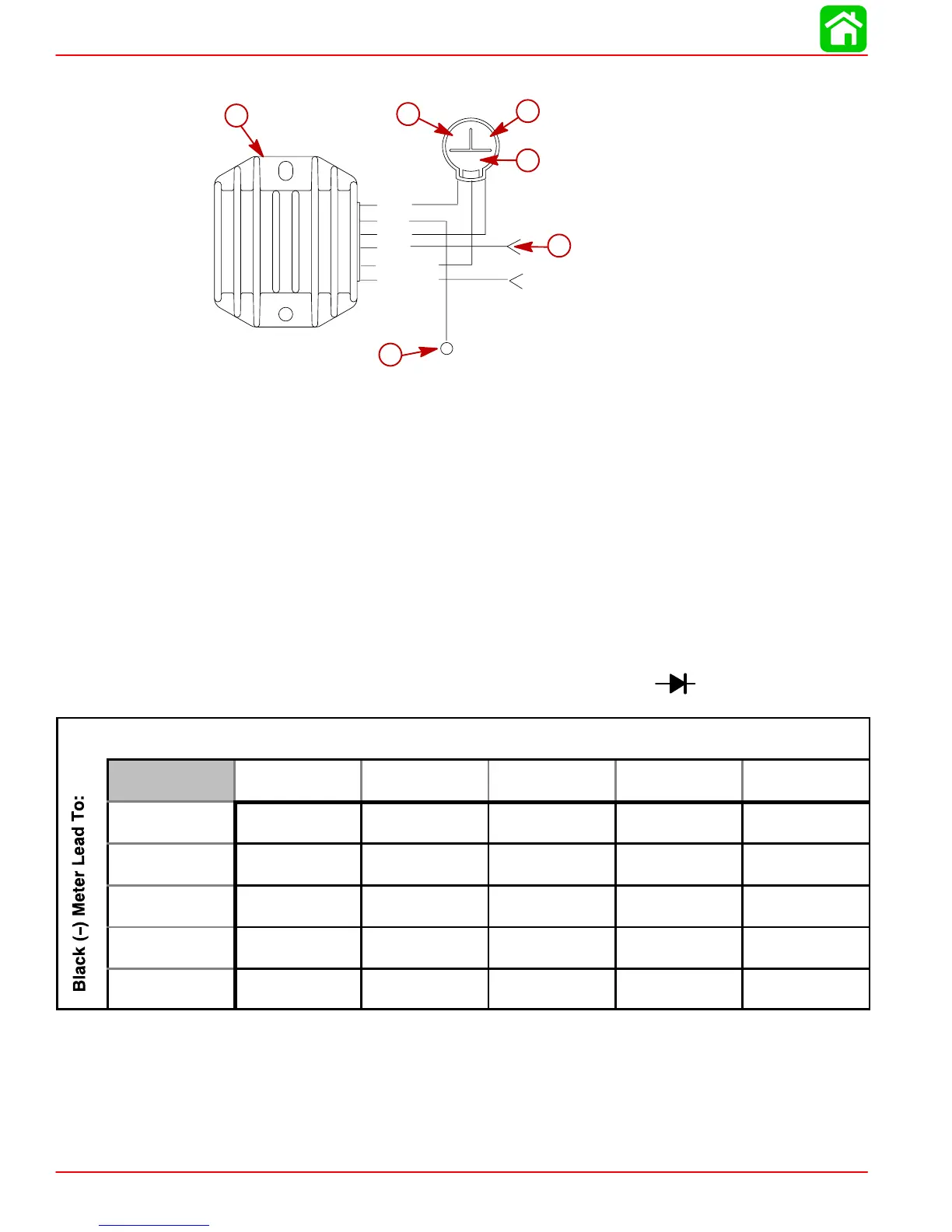
Rectifier/Regulator Diode Test
12
3
GRN
GRN/WHT
BLK
RED
GRN
GRN/WHT
a
c
b
f
e
d
a-Voltage Regulator/Rectifier
b-Test Point - BLK
c-Test Point- GRN (1)
d-Test Point- GRN (2)
e-Test Point- GRN/WHT
f-Test Point- RED
IMPORTANT: When performing a diode test on the rectifier/regulator, use only a digi-
tal meter with the capability of selecting a diode inspection mode.
NOTE: Due to differences in the manufacturing of ohmmeters, the internal polarity may vary.
As a result, the test readings may be a direct reversal of the readings specified. If so, reverse
the meter leads and perform the test again. A slight variance from the listed specification
does not necessarily indicate a defective component.
Rectifier/Regulator Diode Test Chart-Digital Meter ( Scale)
Red (+) Meter Lead To:
BLk GRN (1) GRN (2) GRN/WHT RED
BLK - OUCH OUCH OUCH OUCH
GRN (1) 0.3 to 0.8 - OUCH OUCH OUCH
GRN (2) 0.3 to 0.8 OUCH - OUCH OUCH
GRN/WHT 0.3 to 0.8 OUCH OUCH - OUCH
RED 0.8 to 1.3 0.3 to 0.8 0.3 to 0.8 0.3 to 0.8 -
NOTE: OUCH=OL=Full Meter Deflection
NOTE: All rectifier/regulator leads MUST BE disconnected to obtain accurate diode test
readings.

 Loading...