Home
Mercury
Outboard Motor
45
Mercury 45 Service Manual
4
of 1
of 1 rating
599 pages
Give review
Manual
Specs
To Next Page
To Next Page
To Previous Page
To Previous Page
Loading...
TILLER HANDLE
Page 7B-22
90-828631R3 MARCH 1999
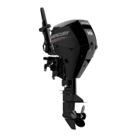
21.
Attach swivel linkage to shift rod. Attach swivel/rod assembly to shift link. Make sure
threads are fully engaged but do not tighten completely
.
22.
Secure bracket and shift rod assembly to side of powerhead with bolts. T
orque bolts to
specified torque.
56250
a
b
c
d
e
f
a-
Bolts, M6x16-(2)
b-
Bracket Assembly
c-
Shift Rod Assembly
d-
Swivel Linkage
e-
Shift Link
f-
Shift Rod
Shift Rod Assembly Bolt T
orque
75 lb-in. (8.5 Nm)
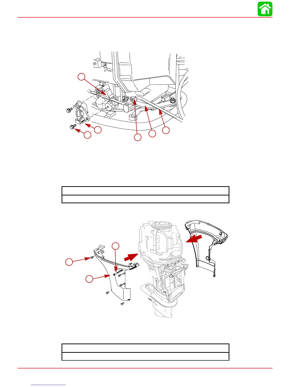
23.
Install lower cowl.
c
a
b
56251
a-
Screws (6)-M6x30
b-
Lower Cowl
c-
Screw-M6x20
Bottom Cowl Bolt T
orque
60 lb-in. (7 Nm)
597
599
Table of Contents
Important Information 1
15
Cleanliness and Care of Outboard Motor
3
Page Numbering
3
Table of Contents
15
Quicksilver Lubricant/Sealant
16
Inspection and Maintenance Schedule
18
Before each Use
18
After each Use
18
Every 100 Hours of Use or Once Yearly, Whichever Occurs First
19
Every 300 Hours of Use or Three Years
19
Before Periods of Storage
19
Corrosion Control Anode
20
Spark Plug Inspection
21
Battery Inspection
21
Timing Belt Inspection
22
Fuse Replacement - Electric Start Models
22
Lubrication Points
23
Checking Power Trim Fluid
24
Changing Engine Oil
25
Oil Changing Procedure
25
Changing Oil Filter
26
Oil Filling
26
Gear Case Lubrication
27
3-1/4 In. (83Mm) Diameter Gear Case
27
4-1/4 In. (108Mm) Diameter Gear Case
28
Gear Case
30
Protecting Internal Engine Components
30
Protecting External Outboard Components
30
Storage Preparation
30
Fuel System
30
Positioning Outboard for Storage
31
Battery Storage
31
Important Information 1
32
Conditions Affecting Performance
33
Weather
33
Boat
34
Engine
35
Following Complete Submersion
36
Fresh Water Submersion (Special Instructions)
36
Salt Water Submersion (Special Instructions)
36
Submerged While Running (Special Instructions)
36
Propeller Selection
37
Propeller Removal/Installation
38
Standard Models
38
General Information
40
Power Trim Operation
40
Power Trim System
40
Trim "In" Angle Adjustment
41
Compression Check
43
Trim Tab Adjustment
43
Analysis
44
Cylinder Leakage Testing
44
Cleaning & Painting Aluminum Propellers & Gear Housings
45
Painting Procedures
45
Decal Application
46
Decal Removal
46
Instructions for "Wet" Application
46
Important Information 1
48
Installation Specifications
49
Selecting Accessories for the Outboard
49
Start in Gear Protection
49
Lifting Outboard
50
Steering Cable
50
Steering Cable Seal
51
Steering Link Rod
51
Installing Outboard - Thumb Screw Models
52
Installing Outboard - Non Thumb Screw Models
53
Wiring Harness
54
Battery Cable Connections
55
Dual Outboards
55
Single Outboards
55
45-50 Hp - Shift Cable Installation
56
Shift and Throttle Cable 45 and 50 Hp Models
56
45-50 Hp - Throttle Cable Installation
58
Trim Tab Adjustment
60
Trim-In Stop Adjustment - Power Trim Models
60
Electrical 2
62
Specifications
63
Special Tools
64
Flywheel
65
Flywheel
66
Electrical Components
67
Electrical Components
68
Capacitor Discharge Unit (CDI)
69
Ignition Component Description
69
Ignition Description
69
Stator Assembly
70
Trigger Coil
70
Flywheel Assembly
71
Ignition Coil
71
Direct Voltage Adapter (DVA)
72
Ignition Test Procedures
72
Ignition Troubleshooting
73
Ignition Diagnostic Procedures
74
Recommended Test
74
Suggested Testing Procedures
74
Resistance Tests
76
Testing Ignition Components
76
Trigger Coil Test
76
Lighting Coil
77
Stator Test (Ignition Charge Coil)
77
Ignition Coil (Primary)
78
Ignition Coil (Secondary)
78
Spark Plug Cap Removal
78
Spark Plug Cap Resistor Test
79
Thermo Switch
79
Flywheel Removal
80
Flywheel Removal and Installation
80
Flywheel Installation
81
Flywheel Without Load Ring & Spacer
81
Flywheel with Load Ring & Spacer
82
(CDI) Unit Removal and Installation
83
Ignition Coil Removal and Installation
84
Rectifier Removal and Installation
85
Stator Removal and Installation
86
Trigger Coil Removal and Installation
87
Electrical 2
88
Specifications
89
Special Tools
90
Starter Motor (S/N-0G472132 & Below)
91
Starter Motor (S/N-0G472133 & UP)
93
Battery
95
Battery Charging System Troubleshooting
95
Operating Engine Without Battery
95
Recommended Battery
95
Battery Charging System
96
Description (10 Ampere)
96
Wiring Diagram (10 Ampere)
96
Alternator System Test (10 Ampere Stator)
97
Stator Ohms Test (Alternator Lighting/Charging Coil)
98
Description
100
Starting System Components
100
Troubleshooting the Starting Circuit
100
Starter Solenoid Test
101
Removal
104
Starter Motor P/N 50-825095 (Top Mounted) . 2B-17
104
Cleaning and Inspection
105
Disassembly
105
Reassembly
109
Installation
112
Removal
113
Starter Motor P/N 50-834749 (Side Mounted) . 2B-26
113
Disassembly
114
Cleaning and Inspection
115
Testing
116
Brush Replacement
118
Reassembly
119
Installation
122
Electrical 2
134
Electric Start Wiring Diagram
135
Tiller Handle Wiring Diagram
136
Commander Remote Control (Electric Start)
137
Commander 2000 Remote Control (Electric Start)
138
Commander 3000 Panel Mount Control
139
Power Trim Switch Wiring Diagram
140
Electric Start Remote Control Model
141
Remote Wiring Harness Connection to Engine
141
Fuel System
142
Fuel Pump
143
Fuel Pump Operation
145
Fuel Pump Removal
146
Fuel Pump
147
Fuel Pump Disassembly
147
Cleaning/Inspection/Repair
148
Fuel Pump Reassembly
149
Fuel Pump
151
Fuel Pump Installation
151
Fuel System
152
Specifications
153
Special Tools
154
Carburetor Linkage
155
Carburetor (40/45)
157
Carburetor (50)
158
Intake
161
Carburetor Adjustments
163
Carburetor Synchronization-Static Adjustment
163
Idle Mixture Screw Adjustment-Static Adjustment
164
Choke Cam Angle Adjustment
165
Fast Idle Adjustment
166
Unloader Adjustment
167
Choke Shutter Closing Adjustment
168
Carburetor Unit Removal
169
Carburetor Link Removal
172
Electrothermal Plunger Removal
173
Solenoid Coil
173
Acceleration Pump
174
Disassembly
174
Removal
174
Fuel Piping Removal
175
Inspection
175
Carburetor
176
Disassembly
176
Silencer Removal
176
Inspection
178
Carburetor Assembly
179
Acceleration Pump
182
Assembly
182
Silencer Installation
182
Installation
183
Fuel Piping Installation
184
Electrothermal Plunger Installation
185
Solenoid Coil Installation
185
Carburetor Link Installation
186
Carburetor Unit Installation
187
Fuel System
189
Carbon Monoxide - CO
190
Controlling Emissions
190
Exhaust Emissions Standards
190
Hydrocarbons
190
Oxides of Nitrogen - Nox
190
What Are Emissions
190
1/3% # Per Year over 9 Model Years
191
Outboard Hydrocarbon Emissions Reductions
191
Stoichiometric (14.7:1) Air/Fuel Ratio
191
Homogenized Charge
192
Stratified Vs Homogenized Charge
192
Stratified Charge
193
Dealer Responsibility
194
Emissions Information
194
Manufacturer's Responsibility
194
Owner Responsibility
194
EPA Emission Regulations
195
Decal Location for 1999 Models
196
Emission Control Information
196
Powerhead
242
Special Tools
243
Crankshaft
245
Cylinder Block
247
Torque Sequence
249
Powerhead Removal
250
Removing Powerhead Components
252
Cylinder Block Disassembly
256
Cylinder Bore
259
Inspection
259
Piston
260
Piston Pin
261
Piston Rings
262
Checking Main Bearing Clearance
263
Oil Pressure Switch
267
Cylinder Block Reassembly
268
Selecting New Main Bearings
268
Main Bearing Installation
269
Installing Connecting Rod Bearings
270
Selecting New Connecting Rod Bearings
270
Connecting Rod Installation
271
Piston Ring Installation
271
Piston Installation
272
Crankshaft Installation
273
Crankcase Cover Installation
275
Exhaust Cover Installation
276
Drive Gear Installation
277
Installing Powerhead Components
278
Cylinder Block/Crankcase
284
Powerhead Installation
284
MID-Section
291
Transom Bracket
292
Swivel Bracket
294
Driveshaft Housing
296
Adaptor Plate
298
Description
299
Anti-Corrosion Grease
300
Steering Arm
300
Bottom Cowl
302
Bottom Cowl Removal
304
Bottom Cowl Installation
305
Co-Pilot Installation
307
MID-Section
310
Special Tools
311
Power Trim Mounting
312
Power Trim
313
Adjustments
315
Theory of Operation
315
Trimming Characteristics
315
Tilting Outboard up and down Manually
316
Trailering Outboard
316
Trim "In" Angle Adjustment
317
Power Trim Flow Diagrams
319
Trim up
319
Tilt up
321
Maximum Tilt
323
Shock Function
329
Shock Function Return
329
Manual Tilt
331
Preliminary Checks
333
Troubleshooting
333
Hydraulic System Troubleshooting Flow Chart
334
Troubleshooting the Power Trim Electrical System
338
Power Trim System Removal
340
Disassembly
341
Shock Rod Removal
341
Shock Rod Disassembly
342
Memory Piston Removal
344
Trim Motor Removal
345
Oil Pump Removal
346
Tilt Relief Valve Removal
346
Pilot Check Valve Assembly Removal
348
Suction Seat Removal
348
Cleaning/Inspection/Repair
350
Trim Motor Electrical Tests
350
O-Ring and Seal Placement
351
Reassembly
351
Power Trim Reassembly
353
Tilt Relief Valve Reassembly
353
Pilot Check Valve Reassembly
354
Suction Seat Reassembly
354
Oil Pump Reassembly
355
Trim Motor Reassembly
356
Shock Rod Reassembly
357
Shock Rod Installation
358
Manual Release Valve Installation
359
Bleeding Power Trim Unit
360
Power Trim System Installation
360
MID-Section
363
Quicksilver Lubricants and Service Aids
364
Special Tools
364
Power Trim Components
366
Adjustments
368
Theory of Operation
368
Trimming Characteristics
368
Tilting Outboard up and down Manually
369
Trailering Outboard
369
Power Trim Flow Diagrams
370
Maximum Tilt
374
Down Circuit
377
Shock Function up
378
Shock Function Return
380
Preliminary Checks
384
Troubleshooting
384
Hydraulic System Troubleshooting Flow Chart
385
Troubleshooting the Power Trim Electrical System
389
Power Trim System Removal
391
Power Trim Disassembly
392
Pump and Components Removal
393
Trim Motor Removal
393
Manifold Removal
394
Shock Rod Disassembly
395
Shock Rod Removal
395
Memory Piston Removal
398
Cleaning/Inspection/Repair
399
Trim Motor Electrical Tests
399
O-Ring and Seal Placement
400
Reassembly
400
O-Ring Sizes
401
O-Ring Description and Sizes
402
Power Trim Reassembly
403
Shock Rod Reassembly
403
Shock Rod Installation
405
Manual Release Valve Installation
406
Trim Limit Assembly Installation
406
Manifold Installation
407
Oil Pump Installation
408
Pressure Operated Assembly Installation
408
Reservoir/Motor Installation
409
Bleeding Power Trim Unit
410
Installation of Power Trim System
410
MID-Section
414
Manual Tilt Components
415
Manual Trim Flow Diagrams
417
Up Circuit
417
Down Circuit
419
Slow Tilt down under High Thrust
421
Under Water Strike (Valves Open)
423
Shock Function (Valves Closed)
425
Shock Function Return
427
Hydraulic System Troubleshooting
429
Manual Tilt System Removal
431
Manual Tilt System Disassembly
432
Accumulator Removal
433
Shock Rod Disassembly
434
Shock Rod Removal
434
Memory Piston Removal
437
Valve Block Removal
437
Valve Block Disassembly
439
Reassembly - O-Ring and Seal Placement
440
Actual O-Ring Sizes
441
Manual Tilt System Cleaning and Inspection
442
Manual Tilt System Reassembly
442
O-Ring Description and Sizes
442
Valve Block Installation
445
Shock Rod Reassembly
446
Shock Rod Installation and Fluid Filling Procedure
448
Filling Procedure Option Two Instructions for Making Retaining Tool
450
Bleeding Manual Tilt System
451
Manual Tilt System Installation
453
Manual Release Valve Adjustment
455
Lower Unit
507
Quicksilver Lubricants and Service Aids
511
General Service Recommendations
516
Draining and Inspecting Gear Lubricant
517
Disassembly
519
Water Pump
519
Bearing Carrier and Propeller Shaft
522
Forward Gear
528
Upper Driveshaft Bearing
530
Oil Sleeve
531
Lower Driveshaft Bearing Race
532
Shift Shaft
533
Forward Gear Bearing Race
535
Trim Tab Adjustment and Replacement
535
Forward Gear Bearing Race
536
Reassembly
536
Shift Shaft
536
Bearing Carrier Reassembly
539
Forward Gear Reassembly
543
Propeller Shaft Reassembly
545
Driveshaft Wear Sleeve Installation
546
Lower Driveshaft Bearing Race Installation
548
Oil Sleeve Installation
549
Upper Driveshaft Bearing Installation
549
Bearing Carrier and Propeller Shaft Installation
557
Water Pump Reassembly and Installation 6B-53
559
Gear Housing Pressure Test
562
Filling Gear Housing with Lubricant
563
Gearcase Installation
564
Trim Tab Adjustment
568
Shift and Throttle Cable Installation to the Outboard
574
Throttle Cable Installation
575
Tiller Handle
578
Tiller Handle Removal
580
Tiller Handle Disassembly
582
Cleaning/Inspection/Repair
584
Tiller Handle Reassembly
584
Tiller Handle Installation
588
Other manuals for Mercury 45
Manual
106 pages
Operator's Manual
75 pages
Operation And Maintenance Manual
103 pages
User Manual
81 pages
4
Based on 1 rating
Ask a question
Give review
Questions and Answers:
Need help?
Do you have a question about the Mercury 45 and is the answer not in the manual?
Ask a question
Mercury 45 Specifications
General
Horsepower
45 HP
Cylinders
3
Starting
Electric
Full Throttle RPM Range
5000-6000 RPM
Steering
Remote
Exhaust
Through Prop
Shaft Length
20 in
Related product manuals
Mercury 40
106 pages
Mercury 4-STROKE
131 pages
Mercury 6 4-Stroke
50 pages
Mercury 5 4-Stroke
50 pages
Mercury 4 4-Stroke
50 pages
Mercury 50 4-Stroke
134 pages
Mercury 25 4-Stroke
72 pages
Mercury 40 4-Stroke
93 pages
Mercury 90 4-stroke
31 pages
Mercury 60 4-Stroke
134 pages
Mercury 40/50 Series
152 pages
Mercury 4-Stroke 9.9 HP
6 pages

 Loading...