Section 5 - Maintenance
90-866938081 MAY 2009 Page 89
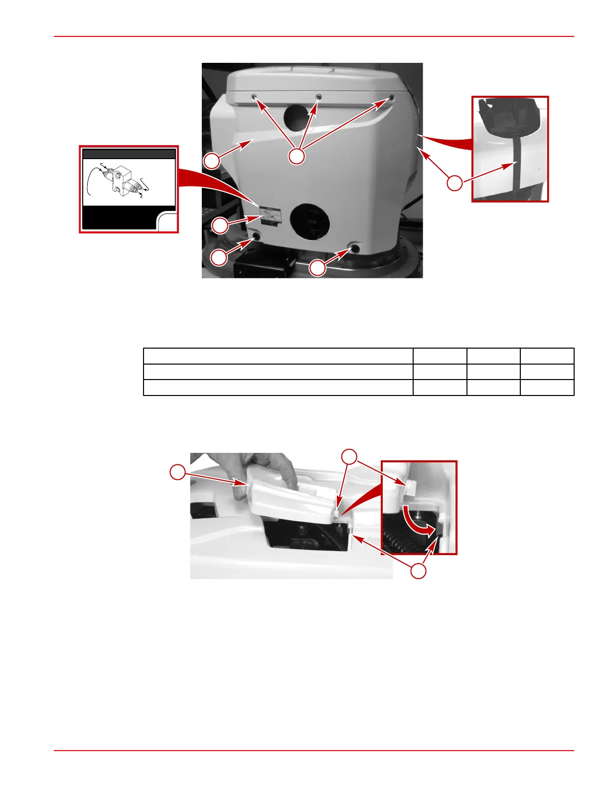
6. Install the port side cover using five screws.
a
a
b
a
c
NOTICE
Push-
Steer to POR T
Push-
Steer to STBD
Push-T rim Down
Push-T rim Up
Stee ring a nd Trim Manua l Override
Buttons.
Refer to Operation
manual for procedure.
8M0041040
d
41329
Typical port side cover
a - Screw (5)
b - Port cover
c - H‑trim
d - Information decal
7. Tighten the three lower and six upper cover screws to specification.
Description Nm lb‑in. lb‑ft
Cover upper screws 10 89 –
Cover lower screws 27 – 20
8. Install the hatch cover.
a. Insert the molded clip on the aft end of the hatch cover under the indented‑edge
of the cover top.
a - Hatch cover
b - Molded clip
c - Indented‑edge
b. Align the hatch cover with the opening in the top cover.
 Loading...


