3.4 Connecting the Swing Head
■■■■■■■■■■■■■■■■■■■■■■
18
■■■■■■■■
855 Robotic Titrosampler
1
Setting up the instrument
■ Start the computer software.
The instrument is automatically recognized. The configuration dia-
log for the instrument is displayed.
■ Make configuration settings for the instrument and its connectors.
More detailed information concerning the configuration of the
instrument can be found in the documentation for the respective
computer software.
3.4 Connecting the Swing Head
Take care to ensure that the Swing Head is connected before the
2.855.0010 and 2.855.0020 instrument versions are set to work. Check
the connection cable.
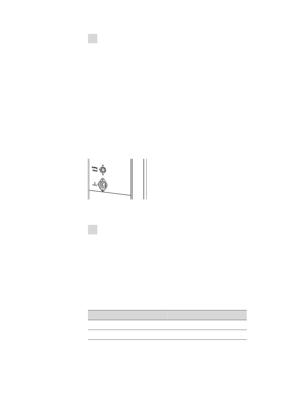
The connection socket (Mini DIN) for the Swing Head drive is located on
the rear of the tower above the stirrer connector.
Figure 8
Connecting the Swing Head
If the Swing Head is not connected, connect it as follows:
1
Plugging in the cable
■ Guide the connection cable of the Swing Head through the guide
chain of the tower (see chapter 3.9, page 27).
■ Plug the Mini DIN plug into the socket 'Swing Head'.
Tower configuration
Make sure that the correct axial distance is entered when configuring the
tower. The axial distance depends on whether the 855 Robotic Titrosam-
pler is used with or without Swing Head. The correct axial distance is
shown in the following table.
Table 1
Axial distance
Operation Axial distance
with Swing Head 196 mm
without Swing Head 166 mm