3.5 Configuring the robotic arm
■■■■■■■■■■■■■■■■■■■■■■
20
■■■■■■■■
855 Robotic Titrosampler
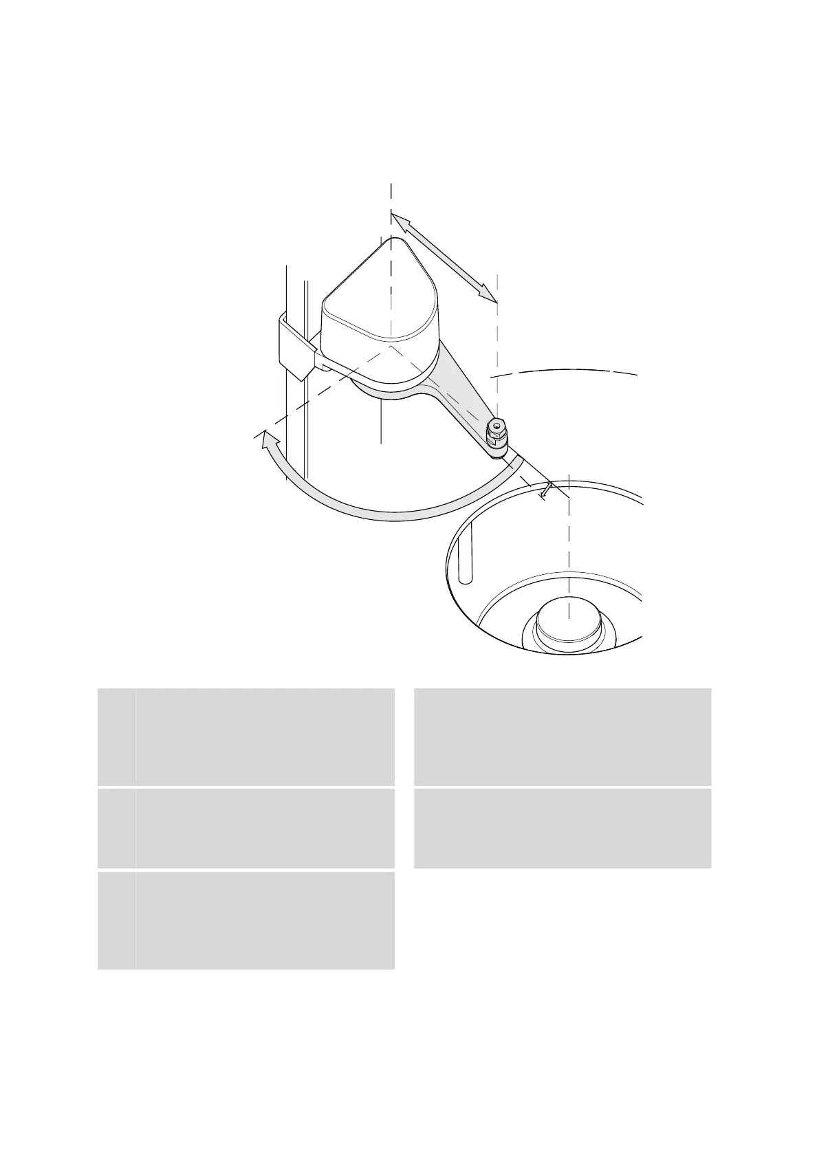
The following figure illustrates the most important configuration data that
needs to be set in the control software to ensure correct usage of a
robotic arm (left-swinging, here).
Figure 10 Configuration data of the robotic arms
1
Swing axis
This runs through the middle of the Swing
Head drive.
2
Swing radius
This is determined by the length of the
robotic arm. The radius runs from the axis of
rotation to the midpoint of the tip of the
robotic arm.
3
Source axis
This runs from the swing axis to the mid-
point of the sample rack and marks the ini-
tial position of the robotic arm.
4
Swing offset
This determines the 0° position of the
robotic arm.
5
Max. swing angle
This stands for the swing range that the
robotic arm can reach. The range runs from
the source axis to the maximum possible
robotic arm position.