4.10 Suppressor
■■■■■■■■■■■■■■■■■■■■■■
82
■■■■■■■■
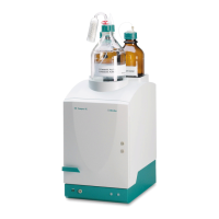
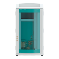
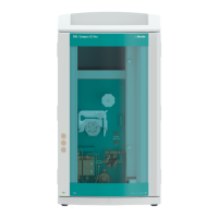
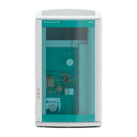
883 Basic IC plus
4.10.3.4 Replacing parts of the suppressor
Parts of the suppressor may have to be replaced in the following cases:
■ Irremediable loss of suppressor capacity (reduced phosphate sensitivity
and/or significant rise in the baseline).
■ Irremediable blockage of the suppressor (solutions can no longer be
pumped through the suppressor).
Both the rotor and the connecting piece can be replaced.
Replacing parts of the suppressor
1
Disconnecting the suppressor from the IC system
■ Switch off the instrument.
■ Disconnect all capillaries of the suppressor from the IC system.
2
Dismantling the suppressor
■ Unscrew the union nut (25-1) from the suppressor drive (25-5).
■ Pull the connecting piece (25-2) out of the suppressor drive
together with the rotor (25-3) and the adapter.
If the rotor and/or the adapter gets stuck in the suppressor drive,
you can push it out as follows:
Put a pointed object into the slot in the suppressor drive and use
it to push out the rotor and/or the adapter.
■ Loosen the connecting piece from the rotor.
3
Cleaning the new rotor
■ Clean the sealing surface of the new rotor (25-3) with ethanol
using a lint-free cloth.
4
Inserting the new rotor
CAUTION
The rotor may be destroyed during start-up if it is not inserted cor-
rectly.
■ Insert the rotor (25-3) into the adapter (see "Inserting the MSM
rotor into the adapter", page 31).