■■■■■■■■■■■■■■■■■■■■■■
4 Operation and maintenance
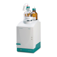
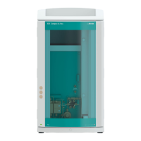
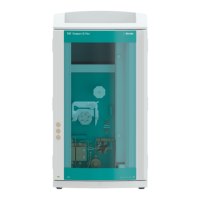
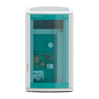
883 Basic IC plus
■■■■■■■■
81
5
Inserting the rotor
CAUTION
Rotor A may be destroyed during start-up if not inserted correctly.
■ Insert the rotor (25-3) into the adapter (see "Inserting the MSM
rotor into the adapter", page 31).
■ Insert the adapter into the suppressor drive (see "Inserting the
adapter into the suppressor drive", page 32).
The rotor's sealing surface is located approx. 4 mm deep inside
the suppressor drive if the adapter with the rotor is inserted cor-
rectly. If this is not the case, the adapter must be moved into the
correct position from below by means of a pointed object.
6
Cleaning the connecting piece
■ Clean the sealing surface of the connecting piece (25-2) with
ethanol using a lint-free cloth.
7
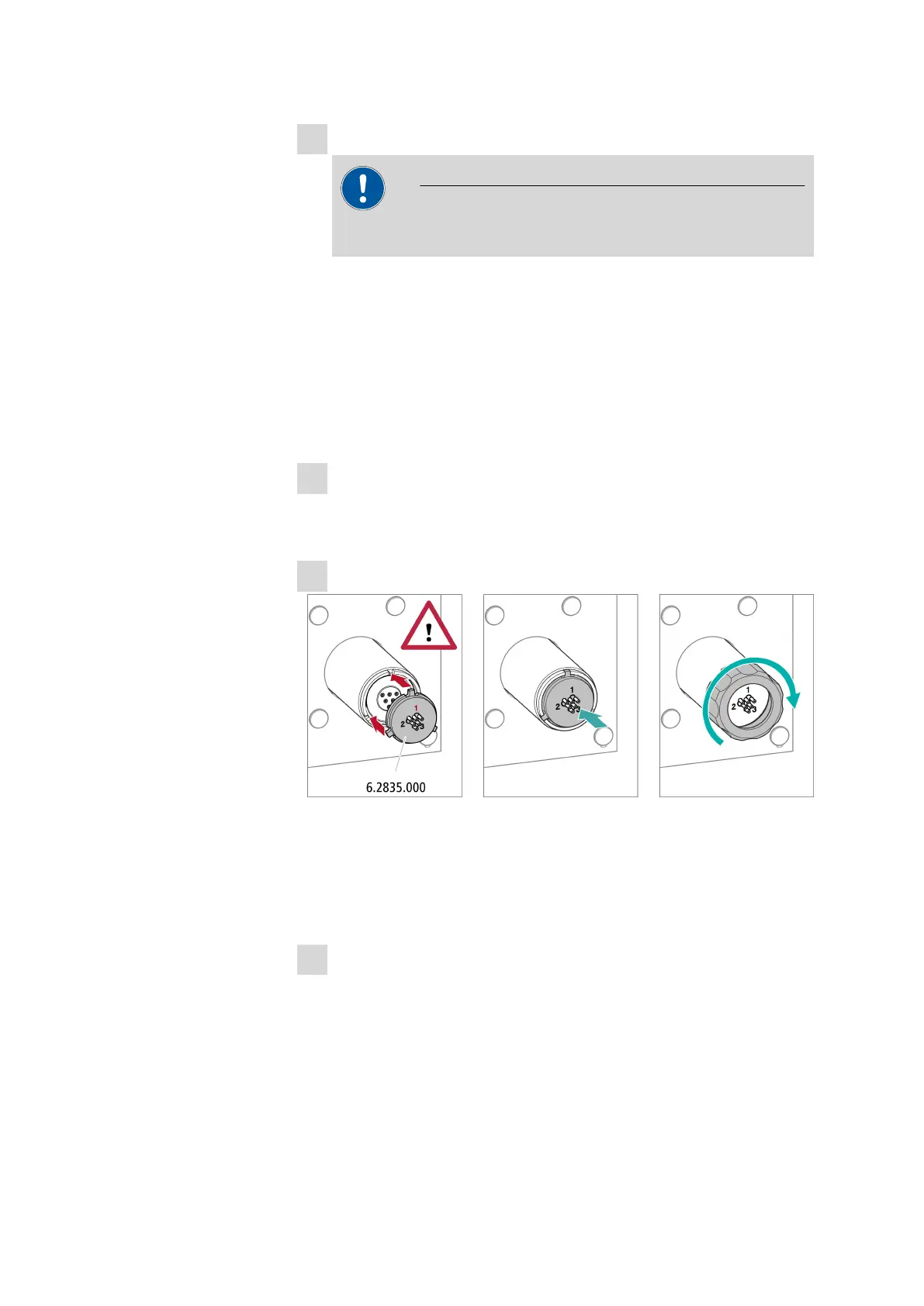
Inserting the connecting piece
■ Insert the connecting piece into the suppressor drive so that con-
nector 1 is on top and the 3 pins of the connecting piece fit into
the corresponding recesses on the suppressor drive.
■ Reattach the union nut (25-1) and tighten by hand (do not use a
tool).
8
Connecting and conditioning the suppressor
■ Reconnect the suppressor to the IC system.
■ Before switching the suppressor over for the first time, rinse each
of the 3 suppressor units with solution for 5 minutes.