6.11 Metrohm Suppressor Module (MSM)
■■■■■■■■■■■■■■■■■■■■■■
88
■■■■■■■■
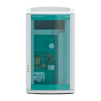
930 Compact IC Flex Oven/SeS/PP (2.930.2500)
For an overview of the rotors, see figure , page 30
■ Insert the rotor (24-3) into the housing (24-4) in such a way that
the tubing connections on the rear of the rotor fit into the corre-
sponding recesses inside the housing and one of the three holes
of the rotor is visible from below in the slot of the housing (24-5).
NOTE
The rotor's sealing surface is located approx. 4 mm deep inside the
suppressor drive if the rotor is inserted correctly.
If this is not the case, then the rotor must be moved into the cor-
rect position using careful turning. If the rotor cannot be turned or
removed, it can be moved into the correct position from below by
means of a pointed object (e.g. a screwdriver).
6
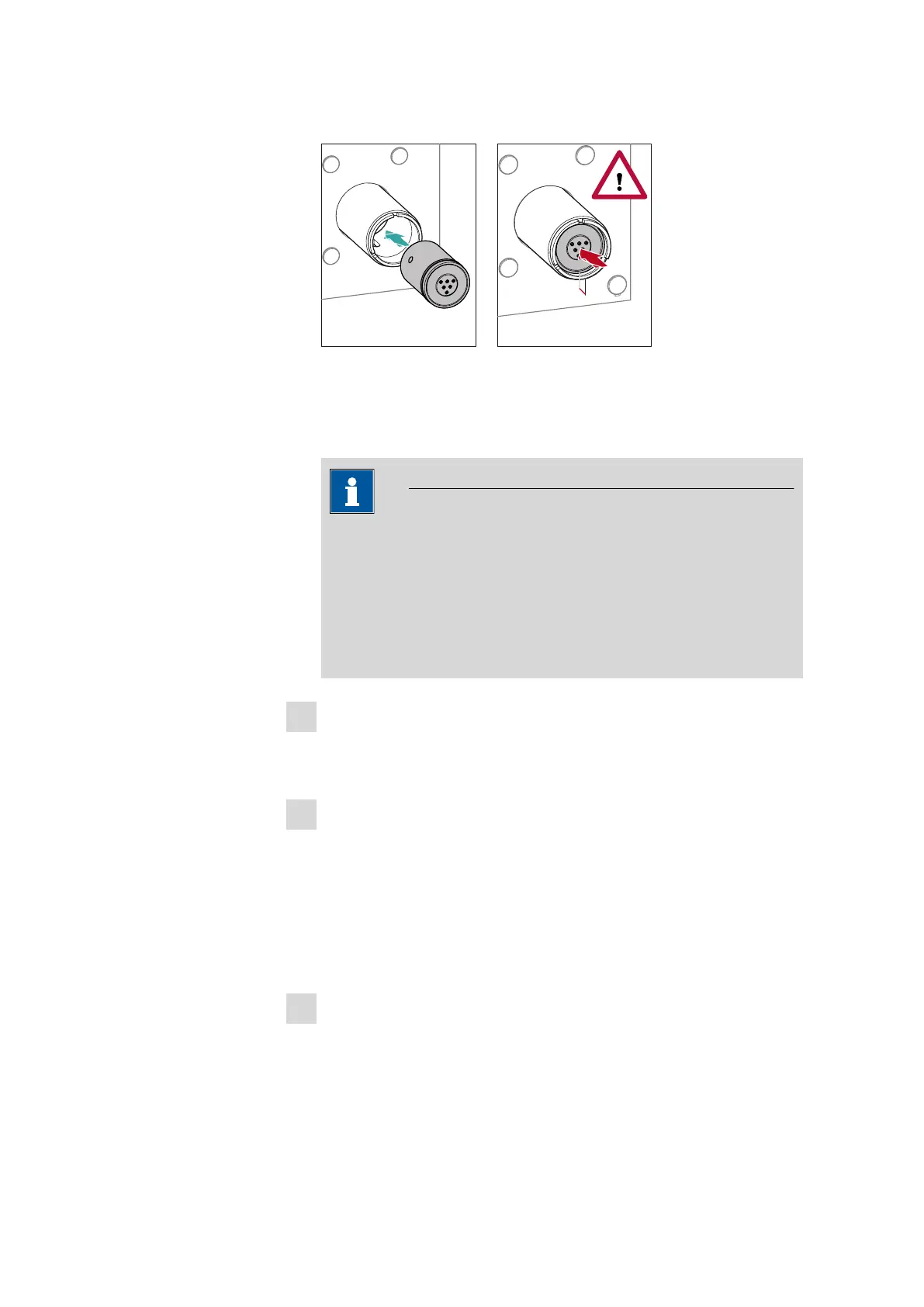
Cleaning the connecting piece
■ Clean the sealing surface of the connecting piece (24-2) with
ethanol using a lint-free cloth.
7
Inserting the connecting piece
See also Chapter 4.11.1, page 31
■ Insert the connecting piece (24-2) into the housing in such a way
that connector 1 is on top and the three pins of the connecting
piece fit into the corresponding recesses on the housing.
■ Reattach the union nut (24-1) and tighten by hand (do not use a
tool).
8
Connecting and conditioning the Metrohm Suppressor Mod-
ule (MSM)
■ Reconnect the MSM to the IC system.
■ Before switching the MSM over for the first time, rinse each of the
three suppressor units with solution for five minutes.