MevaLite
ML-17
90° Corners
Multi-Purpose Panels
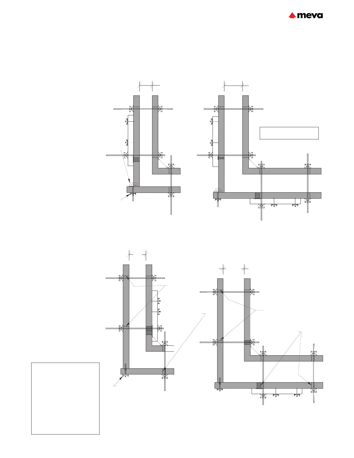
A multi-purpose panel (MPP)
can be used to form 90° outside
corners by connecting a standard
panel with column clamps. The
column clamp is secured with a
flange nut 100 or an articulated
flange nut 15/120. This method
can be used for wall thicknesses
from 6" to 13".
The offset hole pattern in the
MPP allows for wall thickness
changes in 1" increments.
Switching between odd and even
inch increments is accomplished
by simply rotating the MPP 180
degrees.
For wall thicknesses ≤9", the
maximum allowable concrete
pressure is 1350psf (Fig.17.1).
For wall thicknesses
>9" but ≤13", the maximum
allowable concrete pressure is
1100psf (Fig.17.2).
Two multi-purpose panels
connected with tensioning screws
may also be used to form 90°
outside corners for walls from 12"
to 15" thick (Fig.17.3 &17.4).
The maximum allowable concrete
pressure is 1350psf. Additional
locks are required at the panel
joints within 7' of the corner.
Both methods create a tight, rigid
connection.
Fig. 17.1
≤9"
IC
RAIL
RAIL
3" AF
Fig. 17.2
Fig. 17.3 Fig. 17.4
Column
clamp
at each
tie hole
elevation,
typ.
MPP
1.5'
3"AF
MPP
2'
≤13"
12"
15"
1" AF
IC
RAIL
IC
RAIL
3" AF
MPP
MPP
3" AF
Extra panel
joint locks
required
within 7' of
corner per
Fig17.2
IC
3" AF
MPP
MPP
RAIL
3" AF
Extra panel
joint locks
required within
7' of corner per
Fig17.2
Tensioning screw
at each tie hole
elevation, typ.
Maximum allowable concrete
pressure = 1100psf.
Flange nut
100, typ.
MPP
MPP
IC
Description Ref.-No.
ML-inside corners rigid
9’x1’ ..........................................22-505-55
6’x1’ ..........................................22-505-65
4’x1’ ..........................................22-505-75
3’x1’ ..........................................22-505-85
ML-inside corners elastic
9’x1’ ..........................................22-505-60
6’x1’ ..........................................22-505-70
4’x1’ ..........................................22-505-80
3’x1’ ..........................................22-505-90
EA-assembly lock .......................29-205-50
Uni-assembly lock 22 .................29-400-85
Wall formwork
Technical Instruction Manual / June 2022
 Loading...