OM-266409 Page 47
. Hardware is common and
not available unless listed.
272 115-A
1
5
11
7
9 - Figure 8-6
8
10
2
12
3
6
4
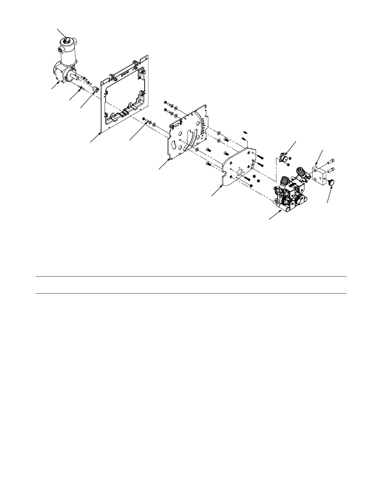
Figure 8-5. Right-Hand Wire Drive Assembly
Description
No.
Mkgs.
No.
Figure 8-5. Right-Hand Wire Drive Assembly (Figure 8-1, Item 15)
Quanti
1 255451 Encoder, Optical 1... .......... .. .................................................
261787 Plug, w/Cable For Encoder 1................ .. ........................................
2 M1 257630 Motor, Gear 1/11HP 40VDC R Angle Lh Boom 1... ... .. .. .......................
3 271862 Stand-off, 10-32 X 1.125 Lg .313 Hex Stl M&M 3... .......... .. .......................
4 253589 Hub, Gear 1... .......... .. .......................................................
5 267153 Insulator, Drive Frame 1... .......... .. ............................................
6 266421 Spacer, Al .166 Id X .250 Od X .562 Lg 3... .......... .. .............................
7 267162 Plate, Drive Mtg Dual 1... .......... .. .............................................
8 267179 Insulator, Motor Mount Rh 1... .......... .. .........................................
9 Figure 8-6 Drive Assy, Wire No Motor Single 1... ........ .. ..................................
10 263322 Screw, Thumb Stl .250−20 x .500 Pld Nylon Head 1... .......... .. ....................
11 256640 Block, Inlet 1... .......... .. ......................................................
12 266403 Pin, Retractable Spring Plunger Plate Mtg 1... .......... .. ...........................
+ When ordering a component originally displaying a precautionary label, the label should also be ordered.
To maintain the factory original performance of your equipment, use only Manufacturer’s Suggested
Replacement Parts. Model and serial number required when ordering parts from your local distributor.