OM-266409 Page 49
. Hardware is common and
not available unless listed.
269 786-A
1
2
3
4
5
6
8
7
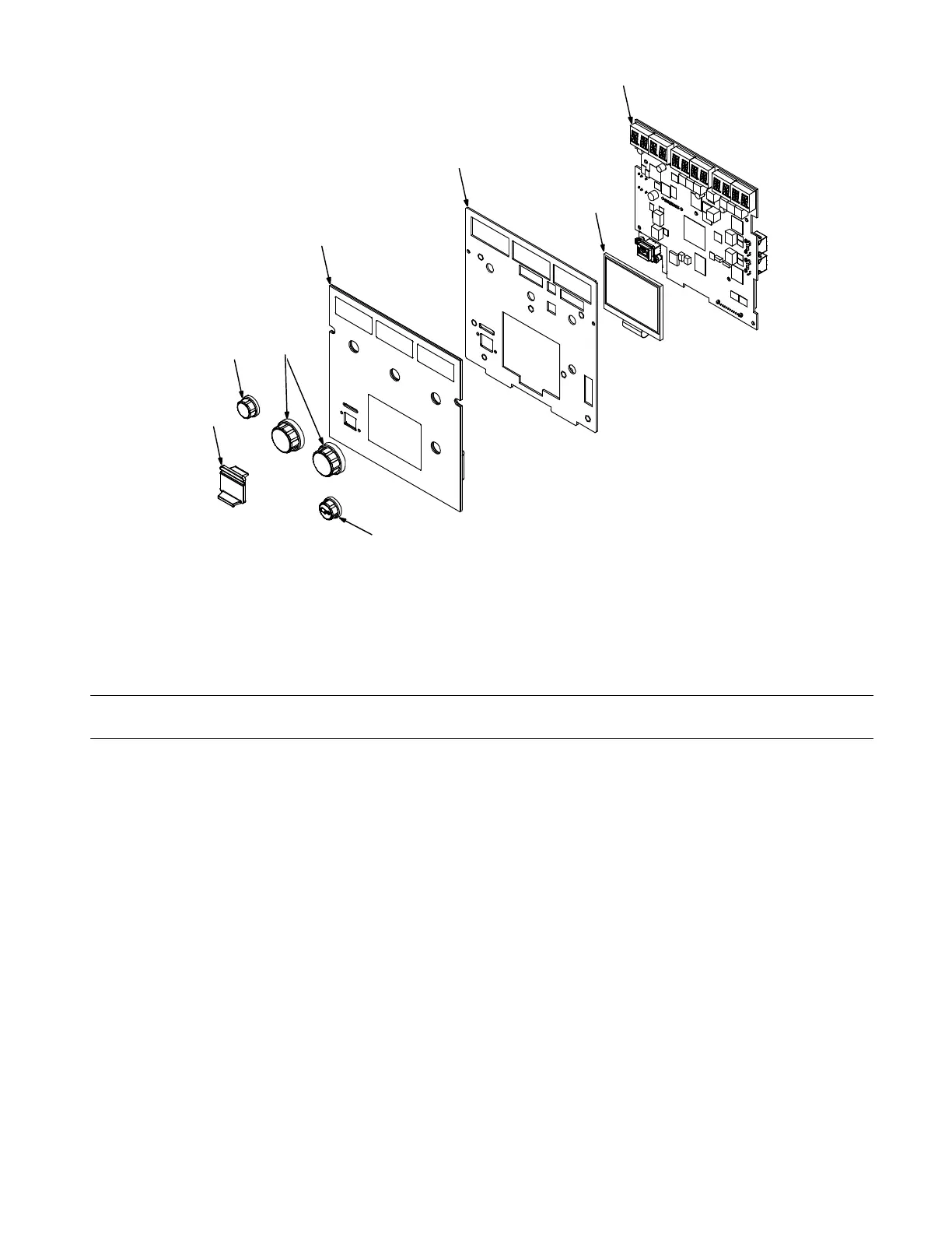
Figure 8-7. User Interface
Description
No.
Mkgs.
266850
No.
Figure 8-7. User Interface (Figure 8-1, Item 13)
Quanti
1 266072 Plate, Ui 1... .......... .. ........................................................
2 266061 Membrane, Switch Control Continuum Ui 1... .......... .. ............................
3 266189 Display, Lcd Tft 320x240 18bit Rgb Pc Tail 1... .......... .. .........................
4 266591 Knob, Encoder 1.250 Dia X 6mm Id Push On W/Spring 2... .......... .. ...............
5 PC34 272938 Circuit Card Assy, Ui W/Program 1... .. . .. ...................................
6 230052 Knob, .840 Dia X 6mm Id W/Spring Clip−4.5 1... .......... .. ........................
7 269555 Knob, .840 Dia X 6mm Id W/Spring Clip−4.5 w/Print 1... .......... .. ..................
8 267343 Cover, USB 1... .......... .. .....................................................
+ When ordering a component originally displaying a precautionary label, the label should also be ordered.
To maintain the factory original performance of your equipment, use only Manufacturer’s Suggested
Replacement Parts. Model and serial number required when ordering parts from your local distributor.