A5/A3™ Service Manual 046-001141-00 5 - 63
Repair and Troubleshooting Pneumatic Circuit System Problems
Tools required:
1. Negative pressure ball (quantity: 1)
2. 3126-06-00 tube plug (quantity: 1)
3. 3126-08-00 tube plug (quantity: 1)
4. 3126-10-00 tube plug (quantity: 1)
5. 106-10-10 adapter connector (quantity: 1)
Test procedures:
1. Turn off the system switch.
2. Pull out No.22 PU tube which connects the CGO assembly to the circuit adapter assembly.
The end of the tube which connect the CGO assembly is pulled out but the other end is not,
as shown below.
3. Occlude the pulled-out tube end by using one 3106-10-00 adapter connector and one 3126-
10-00 tube plug.
FIGURE 5-67
4. Repeat steps 3 through 7 in “4 Leak test of all pipelines on the circuit adapter”. If the test is
failed, it indicates that the connectors of the circuit adapter or seals are damaged. If there is
no leak, insert the pulled-out tubes into the CGO assembly.
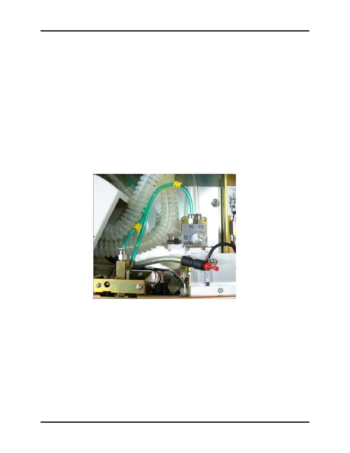
5. Pull out No.52 and 53 PU tubes which connect the O2 flush button assembly and the
vaporizer manifold assembly to the CGO assembly. Disconnect at CGO assy. end.
6. Occlude the pulled-out tube ends by using 3126-06-00 and 3126-08-00 tube plugs, as shown
below.