A5/A3™ Service Manual 046-001141-00 1 - 21
Theory of Operation Gas Flow
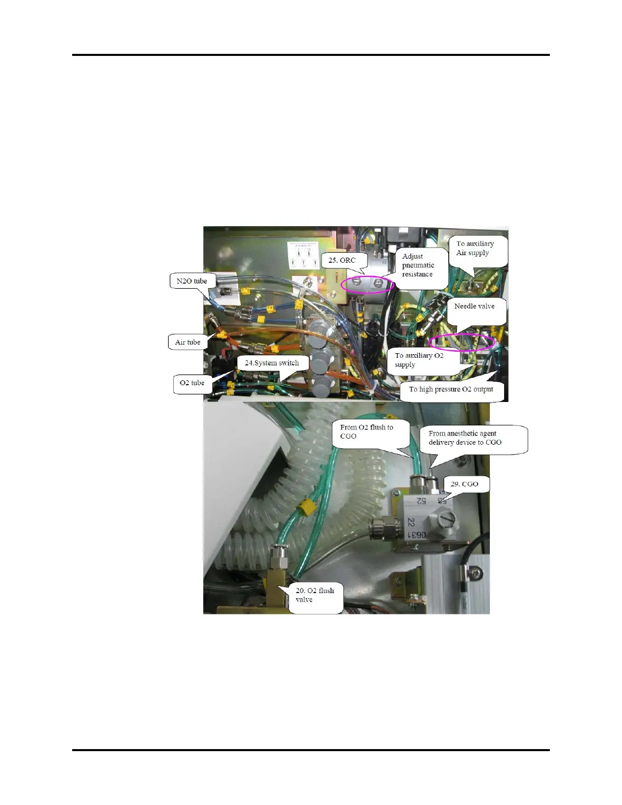
The following picture illustrates how gas supplies are outputted. O2 is divided into four pathways -
system switch (24), O2 flush valve (20), auxiliary O2 supply (51), and high pressure O2 output (44),
respectively. Air enters two pathways - one pathway to the needle valve (58) and the other to the
auxiliary Air supply (3). N2O goes to the ORC (25).
When the system switch (24) is turned on, O2 enters the needle valve (58). When O2 flow is greater
than 300ml, N2O can enter the needle valve (58) through ORC 25. After passing through the needle
valve (58), the pre-set pneumatic resistance (59) controls the O2 and N2O proportions and ensures
the minimum O2 concentration.
FIGURE 1-8 Gas Supply Output