Gas Flow Theory of Operation
1 - 32 046-001141-00 A5/A3™ Service Manual
FIGURE 1-23 AGSS Diagram
The following figure shows the operational theory of the AGSS. The throttling holes reduce the effect
of negative pressure at the AGSS outlet onto the flow at the entrance. The float helps the user
determine if the disposal system meets the requirement for the minimum pump rate. The filter
provides for filtering of foreign substances to prevent the disposal system from being occluded. The
gas reservoir is connected to the air through pressure compensation openings. When positive or
negative pressure occurs inside the gas reservoir, gas is inputted or outputted to ensure pressure
balance inside the system.
The AGSS transfer system is a clear tube with 30 mm conical connectors at both ends. The inlet of the
transfer system is a female 30 mm conical connector and the outlet a male 30 mm conical connector.
The transfer system is connected to the receiving system through the male 30 mm conical connector.
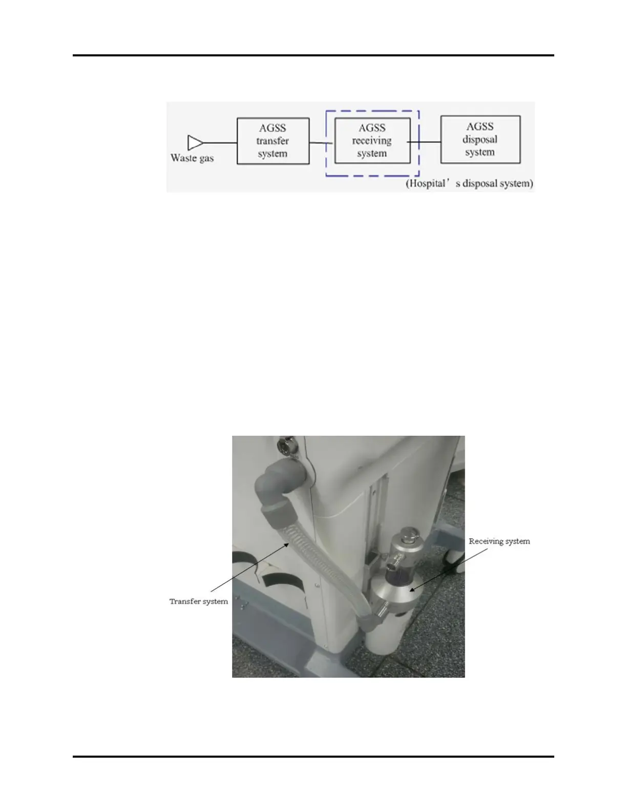
The receiving system is connected to the receiving hose through the 30 mm connector. The
following picture shows the AGSS structure and the connections between the AGSS transfer system,
receiving system, and disposal system.
FIGURE 1-24 AGSS Transfer System