EasyManuals Logo
Home>Mindray>Medical Equipment>A5

Mindray A5 Service Manual

Mindray A5
436 pages
To Next Page IconTo Next Page
To Previous Page IconTo Previous Page
Page #63 background imageLoading...
Page #63 background image
A5/A3â„¢ Service Manual 046-001141-00 1 - 49
Theory of Operation Ventilator UI
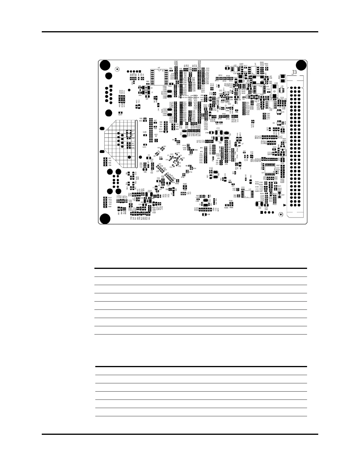
FIGURE 1-48 CPU Board, Bottom View
Network Port, J9
USB Interface, J8
PIN NAME FUNCTION
1 TX+ Positive End of Transmit Signal
2 TX- Negative End of Transmit Signal
3 RX+ Positive End of Receive Signal
4 CT1 No Definition
5 CT1 No Definition
6 RX- Negative End of Receive Signal
7 CT2 No Definition
8 CT2 No Definition
PIN NAME FUNCTION
1VCC USB Power Supply
2 DM0 USB Data Signal – (Negative)
3 DP0 USB Data Signal + (Positive)
4GND Ground
5VCC USB Power Supply
6 DM1 USB Data Signal – (Negative)

Table of Contents

Other manuals for Mindray A5

Questions and Answers:

Question and Answer IconNeed help?

Do you have a question about the Mindray A5 and is the answer not in the manual?

Mindray A5 Specifications

General IconGeneral
BrandMindray
ModelA5
CategoryMedical Equipment
LanguageEnglish

Related product manuals