EasyManuals Logo

Mindray DC-30 Service Manual

Mindray DC-30
213 pages
To Next Page IconTo Next Page
To Previous Page IconTo Previous Page
Page #129 background imageLoading...
Page #129 background image
Structure and Assembly/Disassembly 7-29
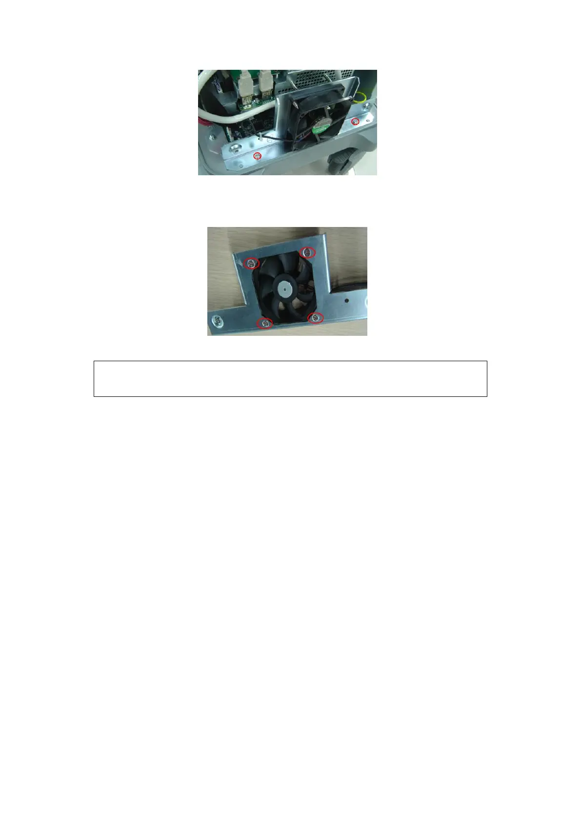
Fig 7-13 Disassemble the main unit fan assembly
4. Remove the fixing M4X8 flat head screws (2 pcs); cut the fan cable ties to remove
the fan.
Fig 7-14 Disassemble the main unit fan
7.4.4 Power Input Assembly
1. Remove the IO board assembly and the rear cover(refer to Chapter 1.3.2 and 1.3.3)
2. Remove the screws M4 X 8 (3pcs) of power input assembly and remove the screw
M4X8 (2pcs) for fixing the grounding cable terminal. Unplug the cable to take down
the assembly upwards.
NOTE:
During installation, pay attention to the main unit fan label, which should
be facing outwards.

Table of Contents

Questions and Answers:

Question and Answer IconNeed help?

Do you have a question about the Mindray DC-30 and is the answer not in the manual?

Mindray DC-30 Specifications

General IconGeneral
DICOMYes
Hard Drive500 GB
Continuous Wave DopplerYes
Tissue Harmonic ImagingYes
Relative Humidity30% to 85% (non-condensing)
Imaging ModesColor Doppler, Power Doppler
Power Supply100-240 V~ 50/60 Hz
Probe Connectors2 active probe connectors
Probe TypesConvex, Linear, Phased Array
Operating Temperature10°C to 40°C
Storage Temperature-20°C to +55°C
Transducer Ports2

Related product manuals