EasyManuals Logo

Mindray DC-30 Service Manual

Mindray DC-30
213 pages
To Next Page IconTo Next Page
To Previous Page IconTo Previous Page
Page #138 background imageLoading...
Page #138 background image
7-38 Structure and Assembly/Disassembly
Fig 7-33 Disassemble the front cover
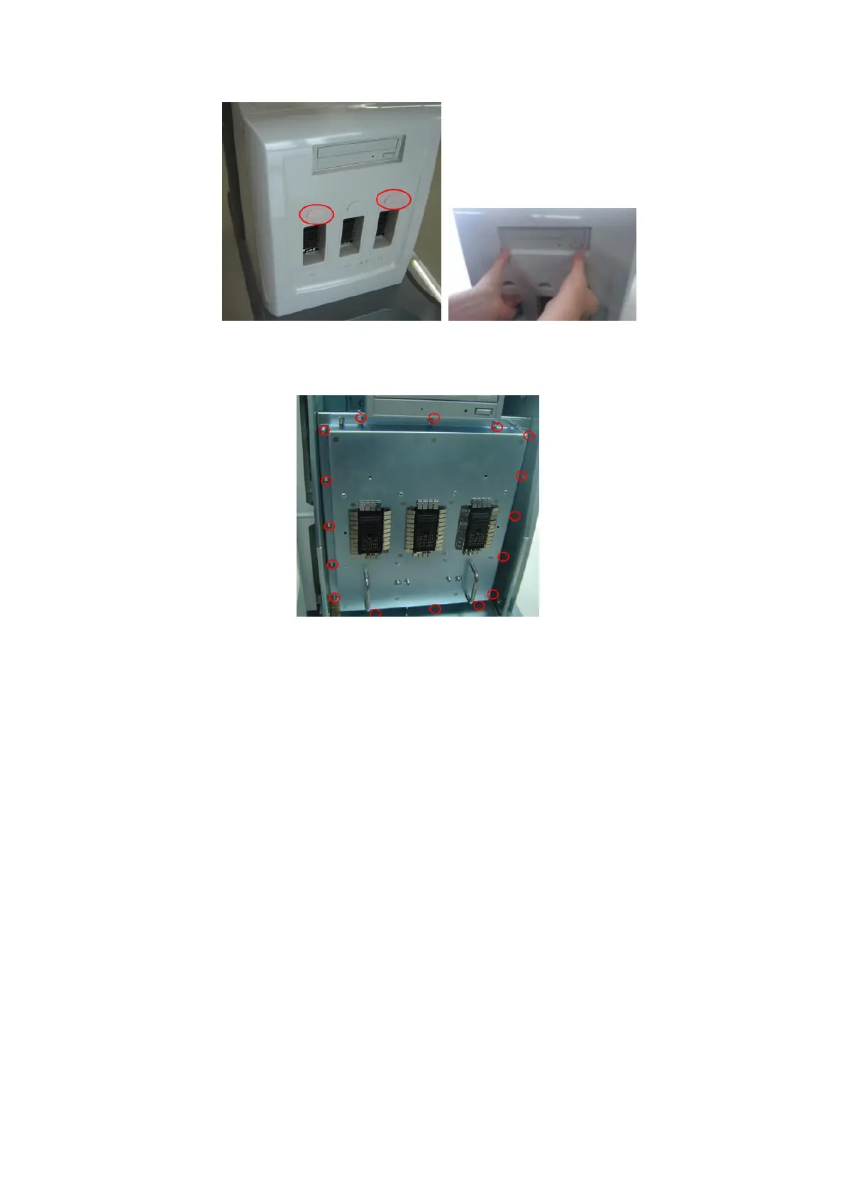
2. Remove the M4x8 screws (16 pcs) which are used to secure the probe board
module, hold the two handles and stably pull out the probe board module.
Fig 7-34 Disassemble the Probe Board Assembly
7.4.8 Left Side-Panel Assembly
Remove the cross panhead screws (M4X8 X 2) fixing the mounting bracket to the left
side-panel. Remove the cross panhead screws (M4X8 X 1) fixing the back mounting ear
to the left side-panel. Remove the cross panhead screw (M4X8 X 1) fixing the front
mounting ear to the left side-panel. Then you can take out the left side-panel.

Table of Contents

Questions and Answers:

Question and Answer IconNeed help?

Do you have a question about the Mindray DC-30 and is the answer not in the manual?

Mindray DC-30 Specifications

General IconGeneral
DICOMYes
Hard Drive500 GB
Continuous Wave DopplerYes
Tissue Harmonic ImagingYes
Relative Humidity30% to 85% (non-condensing)
Imaging ModesColor Doppler, Power Doppler
Power Supply100-240 V~ 50/60 Hz
Probe Connectors2 active probe connectors
Probe TypesConvex, Linear, Phased Array
Operating Temperature10°C to 40°C
Storage Temperature-20°C to +55°C
Transducer Ports2

Related product manuals