11-4 Troubleshooting of Regular Malfunctions
11.3 Image Fault
11.3.1 Module or Board Related
Ultrasound front-end receiving and transmitting physical channels are
64.
High-voltage switch on the probe board
11.3.2 Key Points Supporting Troubleshooting
Key Points Supporting Troubleshooting
Image feature, including dark strips and noise
Images appearance when contact occurs
between different types of probe in different
interface of probe socket.
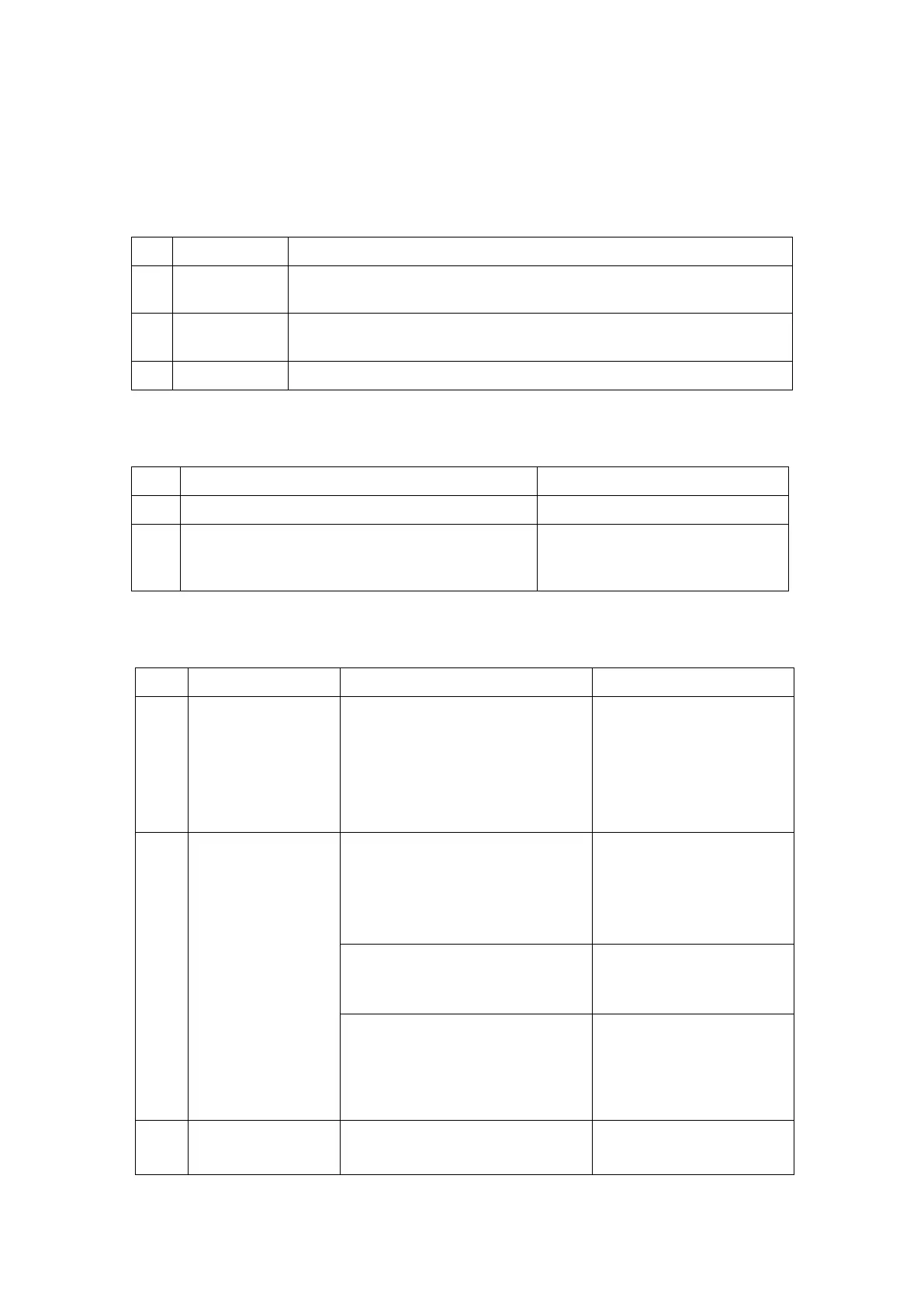
11.3.3 Troubleshooting
NO echo signal in
ultrasonic image
region, The probe
can be indentify
but no echo.
0V or abnormal PHV voltage
output of DC_DC power board;
Main board , DC_DC power
board or probe board may be
fail (low rate);
Confirm the fail cause by
replacing main board,
power module or probe
board.
Dark strips display
on B image
Probe malfunction, e.g. array
damage etc.
Confirm by connecting another
probe.
If several similar dark strips
appear in the image.
Replace the main board
or probe board.
If dark strips appear, also after
replacing the probe socket, dark
strips disappear or change the
place.
Probe malfunction, e.g. array,
rear board, air bubbles and cable