Revision:1.0(2023–5–17)
23
2.3 Product Principle
2.3.1 Overall Architecture of Hardware System
22..33..11..11 Hardware System Diagram
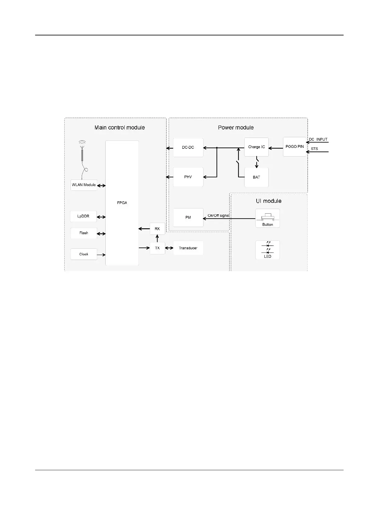
Figure2–1 Block diagram of the overall hardware system architecture
The hardware system of the wireless probe consists of three modules, namely, the main control
module, power module, and UI module. The preceding figure shows the connections between
these modules and their components.
• Main control module:
The main control module implements the scanning function for the ultrasound imaging system,
processes the collected image data, and sends the data to the host computer for imaging
through the WLAN module. This module is composed of the front-end TX module, front-end
RX module, probe head, FPGA, LPDDR, flash storage, clock module, and WLAN module.
• Power module:
The power module is composed of the power management (PM) module, charging port with
pogo pins, charging IC, battery, DC-DC module, and PHV module. The external power source
supplies power to the wireless probe through the charging port. The charging IC charges the
probe battery. The DC-DC module provides various voltage inputs for functional modules. The
PHV module provides programmed voltage for the TX module.
• UI module:
The UI module provides an keypad for users to operate the probe. The keypad provides keys
and indicators.
Diagnostic Ultrasound System
Service Manual
2 Product Knowledge