QX-5000 Series Installation and Operation Manual
25
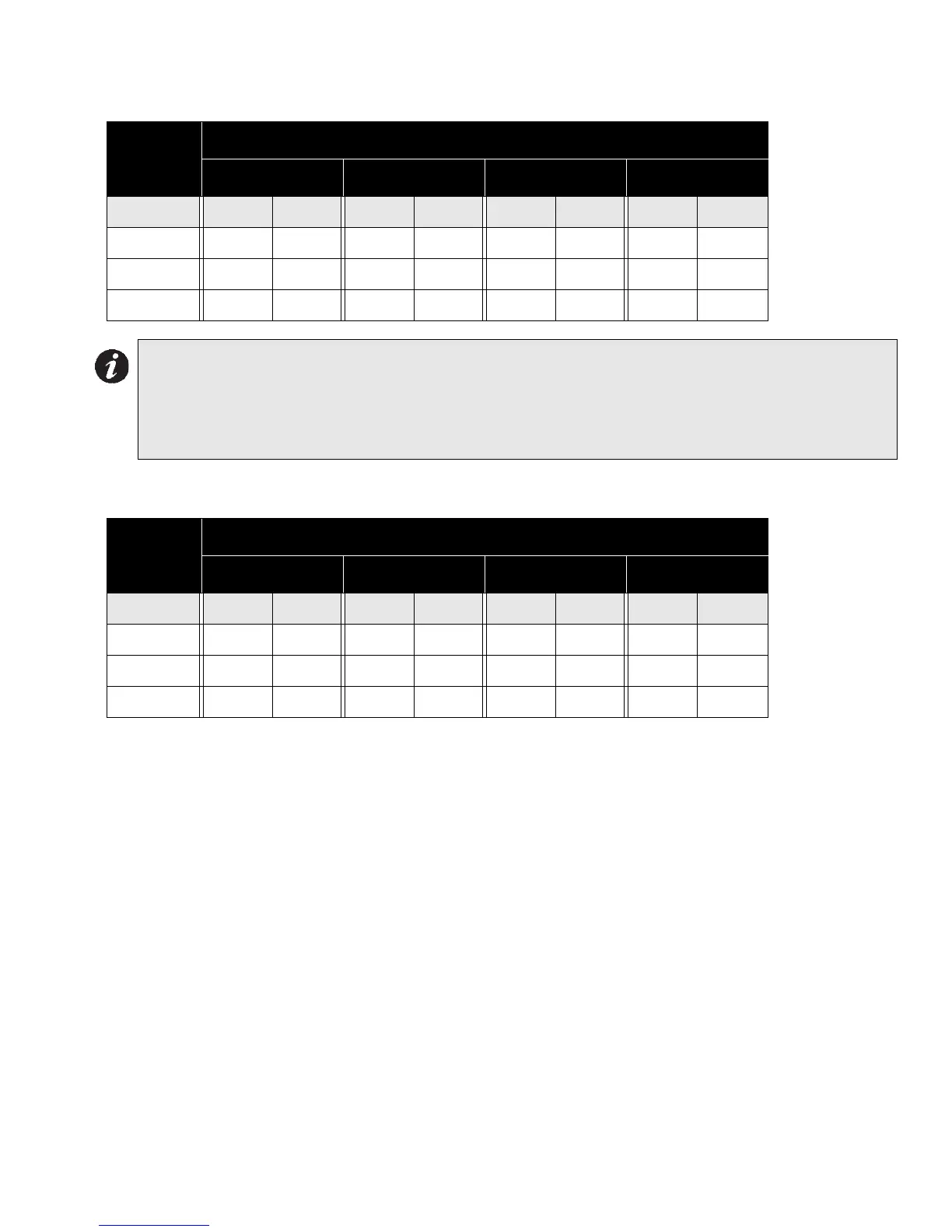
Table 1: Wiring Chart for 70V Speakers
Table 2: Wiring Chart for 25V Speakers
Total
Power
Maximum Wiring Run To Last Device (ELR)
18AWG 16AWG 14AWG 12AWG
Watts ft m ft m ft m ft m
15 2500 762 4000 1219 6000 1828 8000 2438
30 1500 457 2500 762 4000 1219 6000 1828
60 750 228 1200 365 2000 609 3500 1066
Notes for Wiring Charts:
1. For each speaker zone, select the total zone power.
2. Distance shown is calculated to the last speaker, based on the worst case with all speakers lumped
at the end.
3. Calculation is based on a 1db power loss (20%) and a source of 70V or 25V.
Total
Power
Maximum Wiring Run To Last Device (ELR)
18AWG 16AWG 14AWG 12AWG
Watts ft m ft m ft m ft m
15 625 190 1000 305 1500 457 2000 609
30 375 114 625 191 1000 305 1500 457
60 187 57 300 91 500 152 875 267

 Loading...


