QX-5000 Series Installation and Operation Manual
51
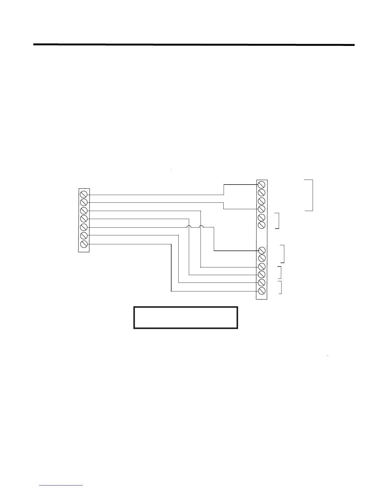
Telephone Module Wiring
If the QMT-5300A or QMT-5302 Master Telephone is used with a QMP-5100B or QMP-5101B Paging Master,
interconnect them as shown in Figure 33, below. If the QMT-5300A or QMT-5302 is being used alone as a single-
zone system, the NP-735 Label is used, and Jumpers are placed on JW1 and JW2 only. The one telephone zone
connects to the TEL-CKT terminals. The 10 Kohm ELR resistor that is shipped with the unit is placed after the last
remote telephone on the zone. If the Master telephone is being used as a multi-zoned system with QZT-5302s, the
NP-736 Label is used, and a Jumper is placed on JW3 only. Telephone zone wiring is done via the QZT-5302s.
The interconnects should be in the same lobby enclosures, or else in adjacent enclosures side by side, connected
via a short metal conduit.
Figure 33: QMT-5300A/QMT-5302 Telephone Master to QMP-5100B/QMP-5101B
Paging Master Wiring
QMT-5300A or QMT-5302
QMP-5100B or QMP-5101B
TBL - A
TBL - B
EXT. AUDIO
LAMP TEST
+
-
24V DC
+
-
LT
COM
+
-
+
-
TEL. CKT (CLASS B )
LAMP TEST
24V DC
EXT. AUDIO
ELR
TRANSMIT
TROUBLE
USE 18AWG or 20 AWG WIRE
OUT
16 or 18 AWG ONLY
+
-
 Loading...


