Configuration
30
Configuration
The process of configuration maps the amplifier zones to the paging selector switches. After all of the audio
cabinet(s) are installed, and modules are inserted and wired, remove the terminal blocks J1 & J2 at the top of the
QIF-5000B to temporarily disconnect the QMP-5100B or QMP-5101B. If the fire alarm is connected and operating, it
will indicate that the QX-5000 system is in trouble. This is normal during configuration.
1. Turn on the AC power to the QX-5000 Audio Cabinet. Do not connect batteries at this point. There will be
troubles indicated; these may be ignored for now.
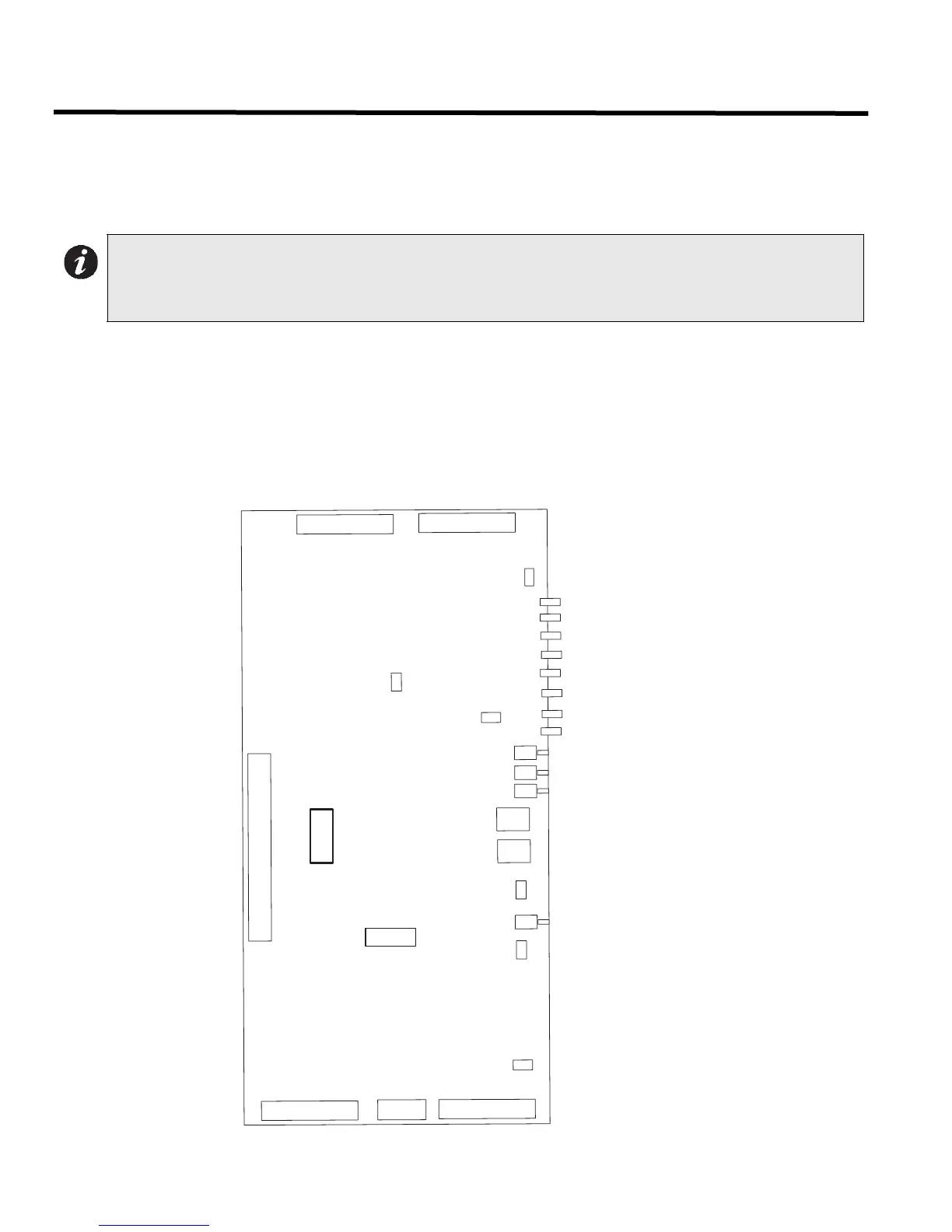
2. Move the Config Jumper JP5 on the QIF-5000B from the 2-3 position to the 1-2 position (moving it down).
3. Press the Audio System Reset button on the QIF-5000B, wait 30 seconds. Only the green AC On LED should
be flashing at this point.
Figure 20: QIF-5000B Interface Module
Note: The term "amplifier" refers to a distinct amplifier; that is a QAA-5160-70/25 contains one 60 watt
amplifier, and a QAA-5230S-70/25 contains two 30 watt amplifiers (two zones to map). Only one
amplifier may be assigned to one paging selector switch. All paging selector switches are numbered
from 01 to 99. For details see Paging Modules section.
J1
J2
J3
J5
J4
JP2
J9
SW1
SW2
JP5
JP3
JP1
J6
CONNECTS TO QMB-5000B AUDIO MOTHERBOARD
A.C. ON
CONNECTIONS TO QMP-5100B OR QMP-5101B MASTER PAGING MODULE
LOBBY/MIC TROUBLE
COMMUNICATION FAIL
GROUND FAULT
SIG. GEN. TROUBLE
FIRE ALARM TROUBLE
ACCESSORY DEVICE TROUBLE
CONFIG-SET
ADVANCE
LAMP TEST
CONFIG SWITCH #1 (1s)
CONFIG JUMPER
QX-5000 SYSTEM RESET
TROUBLE CONNECTION
CONFIG SWITCH #2 (10s)
NOT USED
1
4
1
8
1
8
1
8
1
8
3
2
3
1
21
BATTERY TROUBLE
CONNECTIONS TO FIRE ALARM CONTROL PANEL
FOR CONFIGURATION
DOWNLOADING
J8
J11
 Loading...


