QIF-5000B Configuration Download Procedure
66
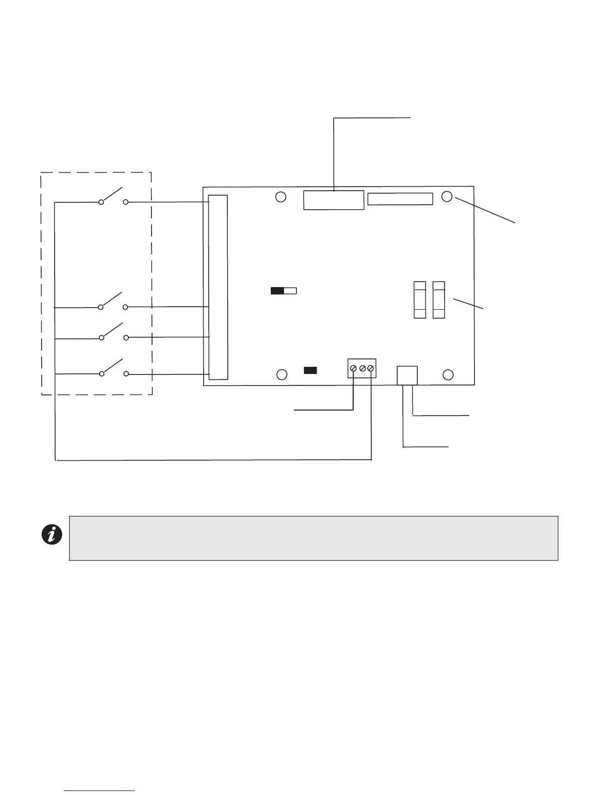
Figure 42: QIF-2000 Interface Wiring Diagram
The QIF-2000 Interface module is used for complex mapping. Inputs 1 through 16 may be programmed via fire
alarm relays to activate different zones with alert or evacuation tones. The mapping is configured at our factory.
Note: If the fire alarm panel is not nearby (beyond 24 ft from the QX-5000), the fire alarm panel must be
addressable, FX-2000 and the use of an addressable relay module CR-6 must be used for the QIF-2000
Interface module.
J7
J8
J6
V+OUT
V+IN
IN 1
IN 2
IN 3
IN 4
IN 5
IN 6
IN 7
IN 8
IN 9
IN10
IN11
IN12
IN13
IN14
IN15
IN16
QIF-2000
L R
JP1
5-WIRE HARNESS TO
QIF-5000 J11
MD-702 CABLE
NORMALLY OPEN CONTACTS
FROM FIRE ALARM
CONFIGURABLE RELAYS ON
THE FA-1000 OR FX-2000
(MUST BE CLOSE CONDUIT)
JP2
J8 NOT USED UNLESS MULTIPLE QIF-2000 INTER
MODULES ARE USED AND THEN THE MD-758 CA
CONNECTED FROM HERE TO J7 OF THE NEXT Q
PUT JUMPER JP1 ON
THE LEFT TWO PINS
TO QIF-5000B
J2-8
TO MASTER PAGING
QMP-5xxx, V+ or
NEXT QIF-2000 V+ IN
F1 FUSE 0.5A
F2 0.65A PTC
F1 F2
6 PIN MOLEX
INPUTS
MOUNTING HOLE
S (4)
EN-OUT
CC -
CC +
FROM
QIF-1000
SEL0
RM-1008A
CLOSE NIPPLE CONNECTED BETWEEN QIF-2000 18AWG
AND THE FIRE ALARM PANEL
 Loading...


