Paging Modules
42
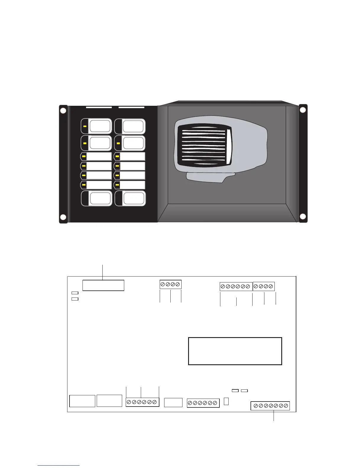
QMP-5101B Master Paging Module
The QMP-5101B Master Paging Module connects via a ribbon cable to the first QZP-5101 Zone Module. It also has
wiring terminals for connection to the QIF-5000B Interface Module in the audio cabinet and to the QMT-5300A or
QMT-5302 Telephone Master.
The two DIP Switches SW1 & SW2 are used for configuration. Do not adjust the field configurable jumpers or
potentiometer; these should be left with their factory default settings.
Figure 26: QMP-5101B Master Paging Module
Figure 27: QMP-5100B and QMP-5101B Master Paging Module Connections and
Location of DIP switches and Terminal Blocks
WARDEN
PAGE
PAGE
INHIBIT
ALL-CALL
ALL-CALL
MINUS
REMOTE
FAILURE
MIC
TROUBLE
MIC
LEVEL
COMMON
TROUBLE
A.C. ON
AMPLIFIER
TROUBLE
CIRCUIT
TROUBLE
RESET
LAMP
TEST
MICROPHONE
DIGITIZED
MESSAGES
P3
P2
SW1
SW2
1
8
111
8
+ S - + S -
MIC
IN
MIC
OUT
PTT
IN
PTT
IN
+ - + -
24VDC
INPUT
+ - + -
24VDC
OUTPUT
RS-485 INTERFACE
INPUT
+ I S I -
OUTPUT
+ I S I -
CONNECTS TO QZP-5101/5102/5103 P1
THESE TERMINALS
ARE CONNECTED TO
THE MICROPHONE
(IN HOUSE)
TBL -A
TBL-B
EXT.AUDIO +
LAMP TEST
24V DC
+ -
CONNECTS TO QMT-5300A/5302 MASTER TELEPHONE
DIP SWITCHES
EXT.AUDIO -
VR2
JP1 JP2
1
1
JP4
JP3
1
1
JUMPERS JP1, JP2, JP3 AND JP4 ARE SET BY DEFAULT
ON PINS 1 AND 2.
VR2 POTENTIOMETER IS USED FOR OVERALL
VOLUME ADJUSTMENT.
 Loading...


