QMP-5100B and QMP-5101B Paging Wiring
44
QMP-5100B and QMP-5101B Paging Wiring
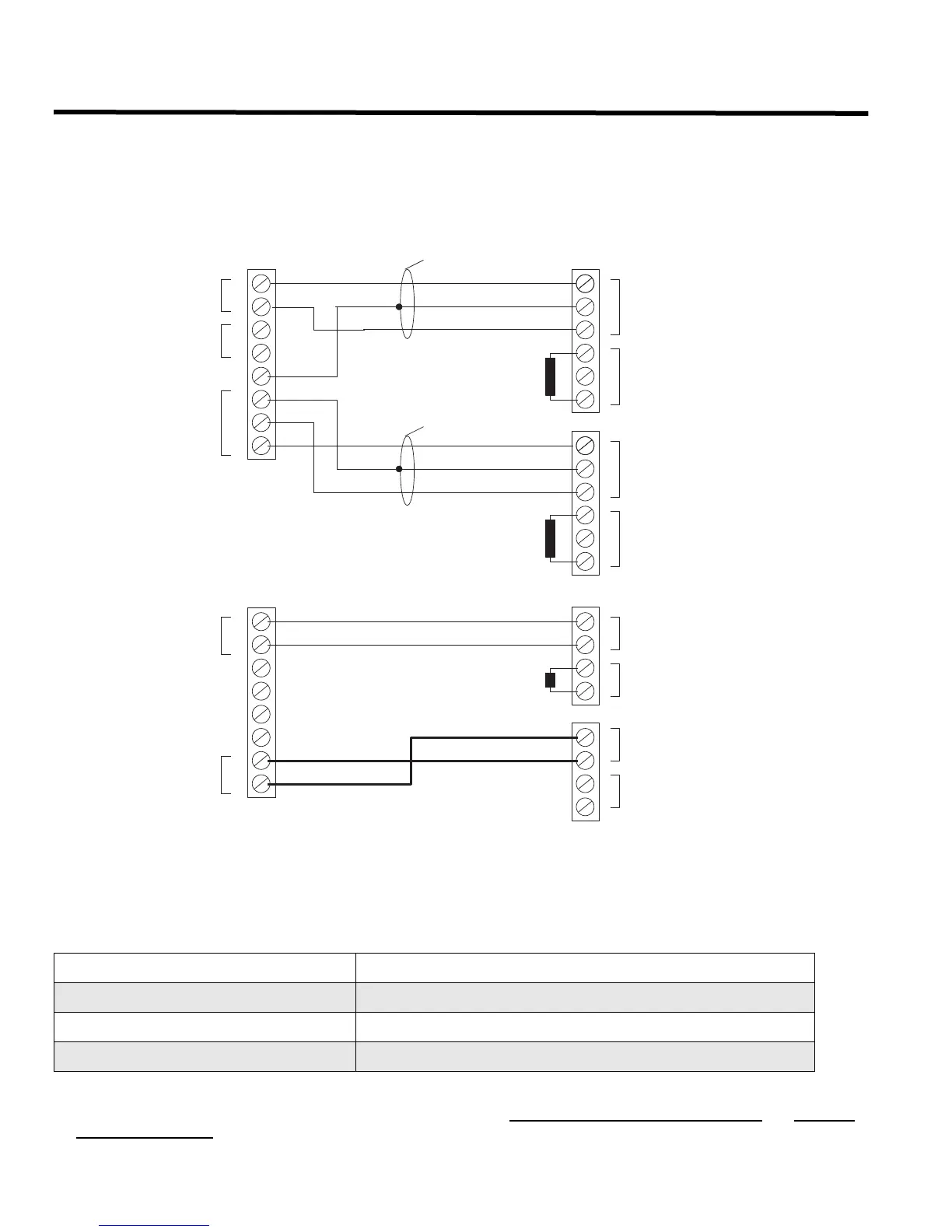
The wiring connection between the QMP-5100B or QMP-5101B Master Paging Module in lobby panel and the QIF-
5000B Interface Module in the audio cabinet is shown below.
Figure 28: QMP-5100B or QMP-5101B to QIF-5000B Wiring
The interface wiring between the QIF-5000B and the QMP-5100B or QMP-5101B are as follows:
The maximum wiring run from the QIF-5000B to the QMP-5100B or QMP-5101B is 1000 feet or 305 metres. All RS-485 must be
point-to-point from the QIF-5000B to the QMP-5100B or QMP-5101B. No star-wiring or T-tapping is allowed.
The 120 ohm
End-of Line Resistor on the RS-485 Output terminals is removed on all except the last wired Module.
MIC+, MIC-, SHLD: 18-22 AWG Twisted Shielded Pair
RS485+, RS485-, SHLD: 18-22 AWG Twisted Shielded Pair
PTT+, PTT-: 18-22 AWG Twisted Pair
24 VDC Power: 18 AWG
FACTORY INSTALLED
3.9K EOL RESISTOR
QMP-5100B/QMP-5101B
QIF-5000B
J1
+
+
-
-
S
S
1
-
A OUT
+
2
3
4
5
6
7
8
S
MIC.
RS485
MIC. INMIC. OUT
TWISTED SHIELDED
PAIR CABLE
FACTORY INSTALLED
3.9K EOL RESISTOR
QMP-5100A/QMP-5101B
+
-
PTT OUT
FACTORY INSTALLED
120R EOL RESISTOR
QMP-5100B/QMP-5101B
+
+
-
-
S
S
RS485 IN
RS485 OUT
QMP-5100B/QMP-5101B
QIF-5000B
J2
1
-
NOT USED
+
2
3
4
5
6
7
8
NOT USED
PTT
TWISTED SHIELDED
PAIR CABLE
S
+
-
MIC.
PTT IN
+
-
+
-
24VDC OUT
24VDC IN
+
-
-
+
24VDC
NOT USED
NOT USED
NOT USED
NOT USED
NOTE: WIRE OUTPUT FROM THE QIF-1000 (IF USED) TO AOUT INPUT TERMINALS ON THE
QIF-5000B. REFER TO THE QIF-1000 INSTRUCTION SHEET FOR SPECIFIC TERMINALS.
+
-
 Loading...


