2.6 Controller Design
All the controllers in the series have the same basic design. The main functional elements and
assemblies are described in the glossary in the appendix.
2.6.1 Input and output circuits
The input circuits use floating inputs. They are electrically isolated from the other circuits of the
PLC with optical couplers. The output circuits use either relay or transistor output technology.
The transistor outputs are also electrically isolated from the other PLC circuits with optical
couplers.
The switching voltage at all the digital inputs must have a certain value (e.g. 24 V DC). This volt
-
age can be taken from the PLC’s integrated power supply unit. If the switching voltage at the
inputs is less than the rated value (e.g. <24 V DC) then the input will not be processed.
The maximum output currents are 2 A on 250 V three-phase AC and non-reactive loads with
relay outputs and 0.5 A on 24 V DC and non-reactive loads.
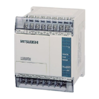
2.6.2 Layout of the MELSEC FX1S base units
The Hardware Controller Design
Training Manual GX IEC Developer 2 - 9
0123
4567
0123
45
IN
OUT
POWER
FX -14MR
1S
RUN
ERROR
X7
X5
X3
X1
S/S
X6
X4
X2
X0
N
L
100-240
VAC
14MR
-ES/UL
Y4
Y2
Y1
Y0
COM0
COM1
COM2
Y3
Y5
24V
0V
MITSUBISHI
Power supply
connection
Terminals for
digital inputs
LEDs for indicating
the operating status
Inter f ace for expansion
adapter boards
Protective cover
RUN/STOP switch
Terminal cover
Connection for the
ser vice power supply
2 analog potentiometers
LEDs for indicating
the input status
Mounting hole
Cutout for adapters or
control panel
Connection for
programming units
Protective cover
LEDs for indicating
the output status
Terminals for
digital outputs

 Loading...