2.9 Extending for Special Functions
A variety of hardware for special functions are available for the MELSEC FX family.
Adapter Boards
Adapter boards are small circuit boards that are installed directly in the FX
1S,FX1N or FX3G con
-
trollers, which means that they don’t take up any extra space in the switchgear cabinet.
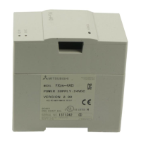
Special Adapter
Special adapters can only be connected on the left side of a base unit of the MELSEC FX
3G,
FX3U andr FX3UC series.
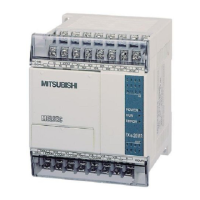
Special function modules
Up to eight special function modules can be connected on the right side of a single base unit of
the MELSEC FX family.
The Hardware Extending for Special Functions
Training Manual GX IEC Developer 2 - 19
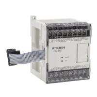
FX1N-2AD
• BY0+
BY0-
BY1+
BY1-
In the case of analog adapter boards, the digital values
generated from the signals coming from the analog input
adapter’s two input channels are written directly to special
registers, which makes it particularly easy to process
them.
The output value for the analog output adapter is written by
the program also to a special register and then converted
by the adapter and sent to the output.
You can install one analog special adapter to a FX3G base
unit with 14 or 24 inputs and outputs.Up to two analog spe-
cial adapter can be mounted to a FX
3G base unit with 40 or
60 inputs and outputs. To a FX
3U or FX3UC base unit up to
four analog special adapters can be connected.
Special adapters do not use any input or output points in
the base unit. They communicate directly with the base
unit via special relays and registers. Because of this, no
instructions for communication with special function mod-
ules are needed in the program.
In addition to analog modules the available special func
-
tion modules include communication modules, positioning
modules and other types. Each special function module
occupies eight input points and eight output points in the
base unit.
Communication between the special function module and
the PLC base unit is carried out via the memory buffer of
the special function module with the help of FROM and TO
instructions.

 Loading...