M800VS/M80V Series Connection and Setup Manual
4 General Specifications
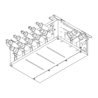
4.4 Control Unit [M80V]
45
IB-1501613-A
Refer to "4.3 Control Unit [M800VS]" for details on the connectors.
Connector
No. Connector name Function No. Connector name Function
(1) USB_F Front-side USB memory I/F (13) RIO2 Remote I/O 2.0 communication
(2) USB_B (14) MENUKEY Menu key I/F
(3) BL Display unit backlight I/F (15) ENC
Encoder input 1 ch
(5 V manual pulse generator input 2 ch)
(4) SDC_F Front-side SD card I/F (16) SKIP SKIP input 8 points
(5) SDC_B Back-side SD card I/F (17) SIO RS-232C communication 2 ch
(6) DCIN 24 VDC input (18) LAN1 Ethernet communication
(7) EMG External emergency stop input (19) LAN2 Ethernet communication
(8) OPTH1 High-speed optical servo communication (20) FG FG terminal
(10) BAT Battery I/F (21) LCD Display unit signal I/F
(11) CJ71 Operation panel I/O unit I/F (22) EXT_P Function expansion unit I/F
(12) RIO1 Remote I/O 2.0 communication (23) TP Touch panel I/F
A
(1)
(2)
(3)
(8)
(5)
(4)
(7)(6)
(10) (13)(11)
(12) (14)
(15) (16) (18)(17) (19) (20)
(21)
(22)
(23)
ArrowA
Note
 Loading...