LED
1
16
18
24 V DC
+
–
Input module
Internal circuit
Opto-coupler
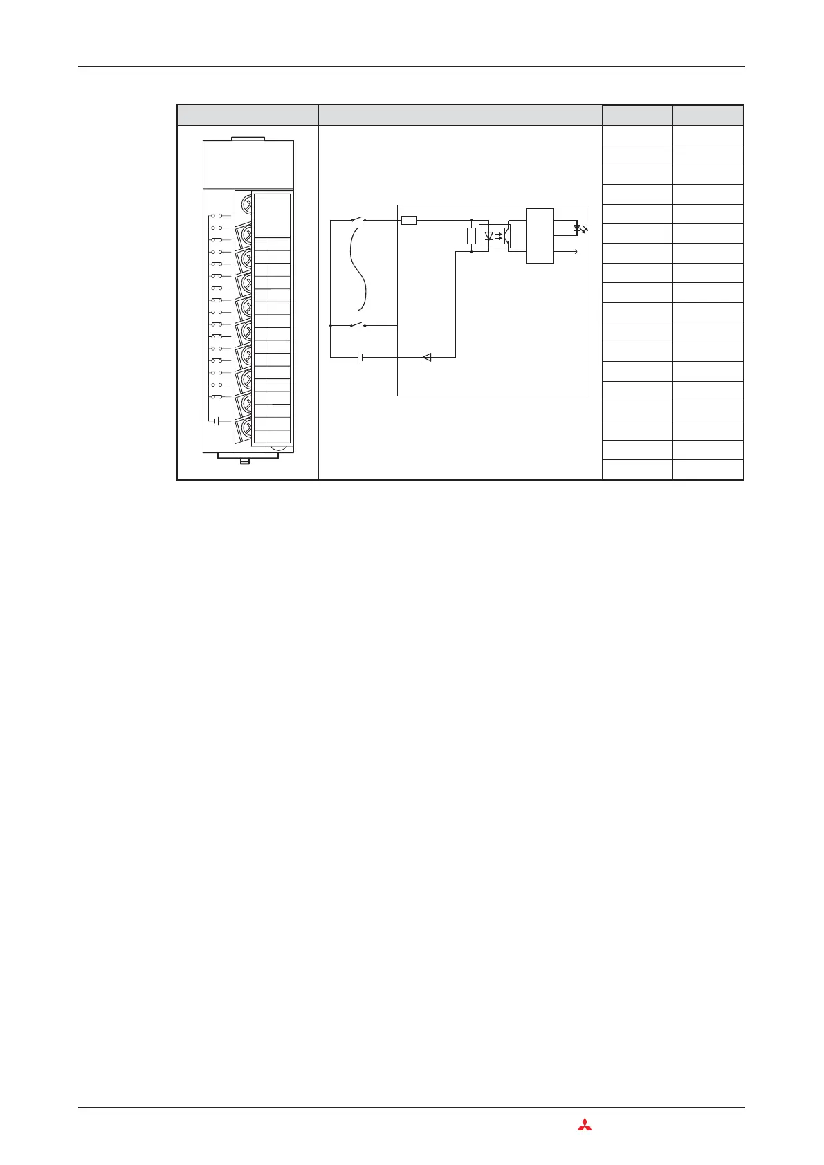
Function of a negative common input module
Referring to the preceding circuit diagram for the QX80, when the push button is closed, the
direction of current flow will be as follows:
쎲 From the +24 Volt terminal of the external power supply, through the push button and into
the terminal 1 of the input module.
쎲 Terminal 1 is connected to the negative pole of the external power supply (terminal 18) via
a resistor and the LED of an opto-coupler. Thus a current flows trough the LED.
쎲 When current flows through the LED it will emit light, which in turn will cause the
Photo-Transistor to turn ON.
쎲 The function of the opto-coupler is to isolate the plant side 24 Volt input circuit from the sen-
sitive 5 Volt PLC processor logic circuitry.This also provides noise immunity from the input.
쎲 With the photo-transistor turning ON, this will cause a signal to be sent to the input image
table, to store the information that the input X0 is ON. The LED at the front side of the input
module lits in this case and indicates the signal state.
3–20 MITSUBISHI ELECTRIC
Das MELSEC System Q Digital Input and Output Modules
1
0
3
5
7
9
B
D
F
2
4
6
8
A
C
E
NC
24VDC
4mA
F
E
D
C
B
A
9
8
7
6
5
4
3
2
1
0
QX80
01234567
89ABC D EF
COM
Appearance Circuit Diagram Terminal Signal
1 X00
2 X01
3 X02
4 X03
5 X04
6 X05
7 X06
8 X07
9 X08
10 X09
11 X0A
12 X0B
13 X0C
14 X0D
15 X0E
16 X0F
17 Vacant
18 COM

 Loading...


