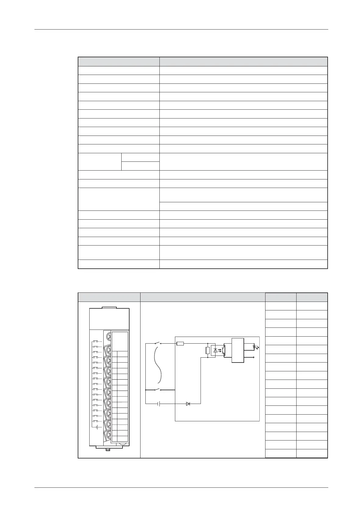
Example for an positive common input module
*
The response times for OFF -> ON and ON -> OFF can not be set separately.
MELSEC System Q Beginners Manual 3 – 21
Digital Input and Output Modules Das MELSEC System Q
Item Specifications
Type of module QX40
Number of input points 16
Isolation method Opto-coupler
Rated input voltage 24 V DC (+20/-15%, ripple ratio within 5%)
Rated input current Approx. 4 mA
Input derating 100 % (All inputs can be switched on simultaneously.)
Inrush current Max. 200 mA for 1 ms (@ 132 V AC)
Voltage / current for ON 19 V DC or higher/ 3 mA or higher
Voltage / current for OFF 11 V DC or lower / 1.7 mA or lower
Input resistance Approx. 5.6 k⏲
Response time
OFF 씮 ON
1, 5, 10, 20, 70 ms (CPU parameter setting, initial setting: 10 ms)*
ON 씮 OFF
Dielectric withstand voltage 560 V AC rms/3 cycles (altitude: 2000 m)
Insulation resistance 10 M⏲ or more (by insulation resistance tester)
Noise immunity
By noise simulator of 500 V p-p noise voltage, 1애s noise width and 25 to
60 Hz noise frequency
First transient noise IEC61000-4-4: 1kV
Groups of inputs 1 group with 16 inputs (Common terminal: terminal 17)
Operation indicator 1 LED for each input
External connections 18-point terminal block (M3 x 6 screws)
Applicable wire size 0.3 to 0.75 mm
2
, core: 2.8 mm OD max.
Internal current consumption
(5 V DC)
50 mA (all input points ON)
Weight 0.16 kg
Appearance Circuit Diagram Terminal Signal
1 X00
2 X01
3 X02
4 X03
5 X04
6 X05
7 X06
8 X07
9 X08
10 X09
11 X0A
12 X0B
13 X0C
14 X0D
15 X0E
16 X0F
17 COM
18 Vacant
1
0
3
5
7
9
B
D
F
-
+
2
4
6
8
A
C
E
NC
24VDC
4mA
COM
F
E
D
C
B
A
9
8
7
6
5
4
3
2
1
0
QX40
01234567
89ABC D EF
LED
1
16
17
24 V DC
+
–
Opto-coupler
Internal circuit
Input module

 Loading...


