Function of a positive common input module
In the preceding diagram, when the push button connected to terminal 1 is closed, the direction
of current flow will be as follows:
쎲
From the +24 Volt terminal of the external power supply to the Common terminal (termi
-
nal 17) .
쎲 Through the LED of the opto-coupler and then through the input resistor network circuit to
terminal 1 (terminal for input X0) of the input module.
쎲 When current flows through the LED, it will then emit light which in turn will cause the
photo-transistor to turn ON.
쎲 The photo-Transistor turning ON causes a signal to be sent to the input image table, to
store the information that the input X0 is ON.The correspondent LED at the front side of the
input module lits in this case and indicates the signal state.
쎲 It then flows through the push button and then back to the negative pole of the external
power supply.
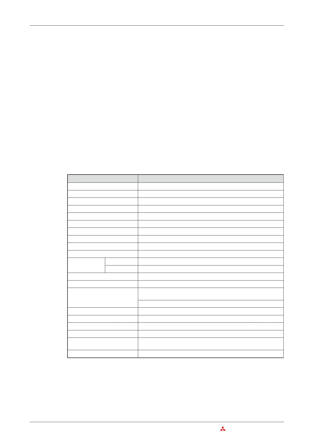
Example for an AC input module
3–22 MITSUBISHI ELECTRIC
Das MELSEC System Q Digital Input and Output Modules
Item Specifications
Type of module QX10
Number of input points 16
Isolation method Opto-coupler
Rated input voltage 100 to 120 V AC (+10/-15 %) 50/60 Hz (앐3Hz) (distortion factor within 5 %)
Rated input current approx. 8 mA @100 V AC, 60 Hz; approx. 7 mA @ 100 V AC, 50 Hz
Input derating refer to derating chart below
Inrush current Max. 200 mA for 1 ms (@ 132 V AC)
Voltage / current for ON 80 V AC or higher/ 5 mA or higher (50 Hz, 60 Hz)
Voltage / current for OFF 30 V DC or lower / 1 mA or lower (50 Hz, 60 Hz)
Input resistance approx. 15 k⏲ @ 60 Hz, approx. 18 k⏲ @ 50 Hz
Response time
OFF 씮 ON 15 ms or less (100 V AC, 50 Hz, 60 Hz)
ON 씮 OFF 20 ms or less (100 V AC, 50 Hz, 60 Hz)
Dielectric withstand voltage 1780 V AC rms/3 cycles (altitude: 2000 m)
Insulation resistance 10 M⏲ or more (by insulation resistance tester)
Noise immunity
By noise simulator of 1500 V p-p noise voltage, 1애s noise width and 25 to
60 Hz noise frequency
First transient noise IEC61000-4-4: 1kV
Groups of inputs 1 group with 16 inputs (Common terminal: terminal 17)
Operation indicator 1 LED for each input
External connections 18-point terminal block (M3 x 6 screws)
Applicable wire size 0.3 to 0.75 mm
2
, core: 2.8 mm OD max.
Internal current consumption
(5 V DC)
50 mA
Weight 0.17 kg

 Loading...


