Triac Output Modules
Digital output modules can switch voltages of 100 to 240 V AC. As with all other output configu-
rations the physical output is isolated by opto-coupler. The response of the triac is obviously
faster than the relay with a response time of 1ms to turn ON and 10 ms to turn OFF again.
Since the load of an triac output is restricted to 0.6 A, care should be taken when configuring
your system so as not to overload the output circuitry.
Because the leakage current in a triac output circuit is greater than that of a relay circuit, care
must be taken as this current is enough to cause indicators to illuminated and some miniature
relays to hold their operation. In fact, this is one of the most frequent causes of electric shock
when working in cabinets controlled by PLC’s.
P
DANGER:
Special care must be taken when working in live environments with output circuits con-
trolled by triac devices, even if the outputs are apparently turned off!
3–26 MITSUBISHI ELECTRIC
Das MELSEC System Q Digital Input and Output Modules
1
0
3
5
7
9
B
D
F
2
4
6
8
A
C
E
NC
24VDC
240VAC
2A
COM
F
E
D
C
B
A
9
8
7
6
5
4
3
2
1
0
L
L
L
L
L
L
L
L
L
L
L
L
L
L
L
L
QY10
01234567
89ABC D EF
Internal
Circuit
LED
230 V AC
Output module
1
16
17
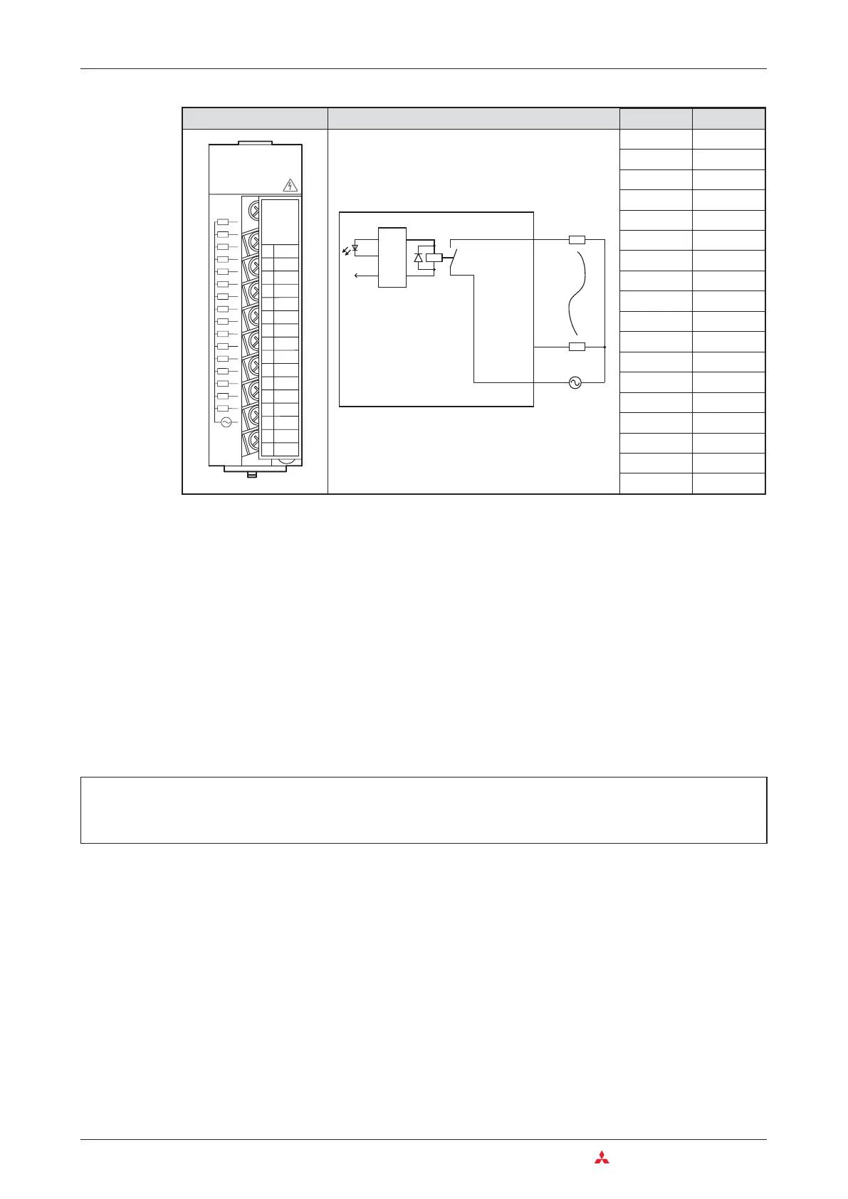
Appearance Circuit Diagram Terminal Signal
1 Y00
2 Y01
3 Y02
4 Y03
5 Y04
6 Y05
7 Y06
8 Y07
9 Y08
10 Y09
11 Y0A
12 Y0B
13 Y0C
14 Y0D
15 Y0E
16 Y0F
17 COM
18 Vacant

 Loading...


