EasyManua.ls Logo

Mitsubishi MELSEC System Q User Manual

Mitsubishi MELSEC System Q
170 pages
To Next Page IconTo Next Page
To Previous Page IconTo Previous Page
Page #52 background imageLoading...
Page #52 background image
Analog input modules for temperature acquisition
Temperature values can be acquired with two different sensor technologies: Pt100 resistance
thermometers and thermocouples.
Pt100 resistance thermometers
These devices measure the resistance of a platinum element, which increases with tem-
perature. At 0°C the element has a resistance of 100C (thus the name Pt100). The resis-
tance sensors are connected in a three-wire configuration, which helps to ensure that the
resistance of the connecting cables does not influence the measurement result.
The maximum measurement range of Pt100 resistance thermometers is from -200°C to
+600°C but in practice it also depends on the capabilities of the temperature acquisition
module being used.
Another metal used for resistance thermometers is nickel (Ni100). In this case the mea-
surement range is smaller (-60C to 180C).
Thermocouples
These temperature measurement devices take advantage of the fact that a voltage is gen-
erated when heat is applied to an element made of two different metals. This method thus
measures a temperature with the help of a voltage signal.
There are different kinds of thermocouples.They differ in their thermal electromotive force
(thermal e.m.f.) and the temperature ranges they can measure.The material combinations
used are standardized and are identified by a type code.Types J and K are both commonly
used. Type J thermocouples use a combination of iron (Fe) and a copper/nickel alloy
(CuNi), type K thermocouples use a NiCr and Ni combination.In addition to their basic con
-
struction thermocouples also differ in the temperature range they can measure.
Thermocouples can be used to measure temperatures from -200°C to +1,200°C.
3–32 MITSUBISHI ELECTRIC
Das MELSEC System Q Special Function Modules
Analog input Analog input range
Selectable input
ranges
Input
channels
Module
Voltage -10 to +10 V
1 to 5 V
0 to 5 V
0 to 10 V
-10 to +10 V
8 Q68ADV
Current 0 to 20 mA
0 to 20 mA
4 to 20 mA
8 Q68ADI
Voltage or current
(can be selected for each
channel)
-10 to +10 V
0 to 20 mA
As for 68ADV and
Q68ADI
4 Q64AD
3
2
1
A/D
0~±10V
0~20mA
4
5
6
7
8
9
10
11
12
13
14
15
16
17
18
C
H
1
C
H
2
C
H
3
C
H
4
I+
V+
I+
V+
I+
V+
I+
V-
SLD
V-
SLD
V-
SLD
V-
SLD
A.G.
(FG)
RUN
ERROR
V+
Q
6
4
A
D
The analog input modules of the MELSEC System Q combine a high
resolution (0.333 mV / 1.33 µA) with a high conversion speed (80 µs per
channel).
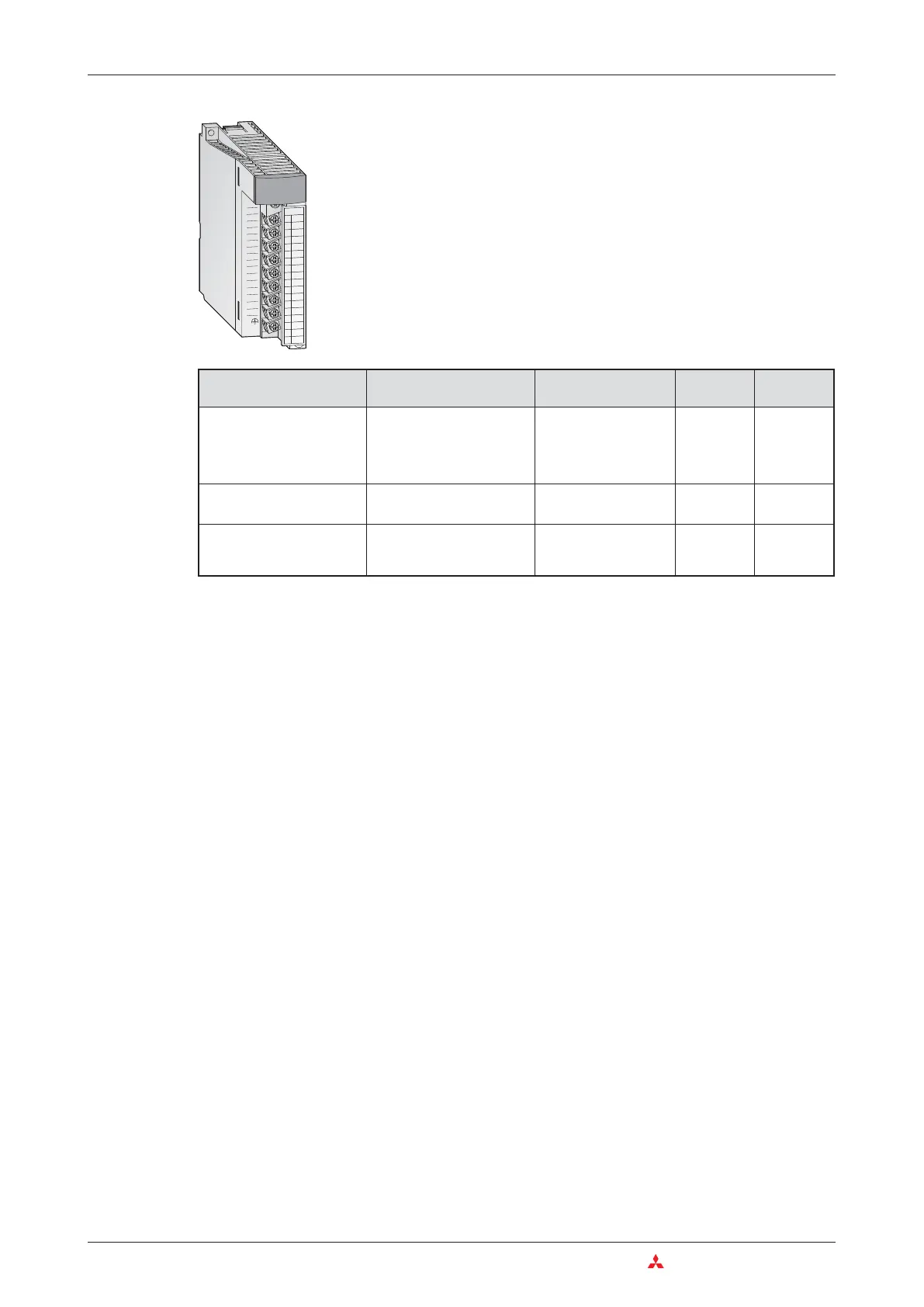
All modules provide removable screw terminal blocks.

Table of Contents

Other manuals for Mitsubishi MELSEC System Q

Question and Answer IconNeed help?

Do you have a question about the Mitsubishi MELSEC System Q and is the answer not in the manual?

Mitsubishi MELSEC System Q Specifications

General IconGeneral
BrandMitsubishi
ModelMELSEC System Q
CategoryController
LanguageEnglish

Summary

2 Programmable Logic Controllers

3 The MELSEC System Q

3.1 System Configuration

Details the modular structure and components of the MELSEC System Q.

3.2 Base Units

Describes available base units for mounting MELSEC System Q modules.

3.3 Power Supply Modules

Explains the function and types of power supply modules for MELSEC System Q.

3.4 The CPU Modules

Introduces different types of CPU modules available for the MELSEC System Q.

3.5 Digital Input and Output Modules

Describes the types and functions of digital input and output modules.

3.5.1 Digital Input Modules

Explains the specifications and considerations for digital input modules.

3.5.2 Digital Output Modules

Details the types, advantages, and specifications of digital output modules.

3.6 Special Function Modules

Introduces various special function modules for MELSEC System Q automation.

3.6.1 Analog Modules

Explains analog input and output modules and selection criteria.

3.7 Networks and Network Modules

Covers networking concepts and modules for MELSEC System Q communication.

3.7.4 Network Modules

Explains ETHERNET and MELSECNET modules for system communication.

4 An Introduction to Programming

4.7 The Basic Instruction Set

Provides a reference to basic instructions used in MELSEC PLC programming.

4.8 Safety First!

Emphasizes crucial safety precautions when working with PLCs and systems.

4.9 Programming PLC Applications

Demonstrates PLC application development with a practical example.

4.9.1 A rolling shutter gate

Presents a detailed example of programming a rolling shutter gate control system.

4.9.2 Programming

Guides through the process of creating a new PLC project and assigning variables.

5 Devices in Detail

5.1 Inputs and Outputs

Explains how PLC inputs and outputs connect to the controlled process.

5.2 Relays

Details the function and types of relays (normal and latched) in PLC programs.

5.3 Timers

Describes programmable internal timers, their function, and types (low/high speed, retentive).

5.4 Counters

Explains internal counters for programming counting operations and their features.

5.5 Registers

Covers registers for storing measurements and calculation results (16-bit and 32-bit).

5.5.1 Data registers

Details data registers used for memory storage in PLC programs.

6 More Advanced Programming

6.1 Applied Instructions Reference

Provides a reference for advanced PLC instructions beyond basic logic.

6.2 Instructions for Moving Data

Explains instructions for moving data between registers and devices.

6.2.5 Exchanging data with special function modules

Details using FROM/TO instructions for data exchange with special function modules.

6.3 Compare Instructions

Explains instructions for comparing values (numerical, string) in PLC programs.

6.4 Math Instructions

Covers basic arithmetic operations like addition, subtraction, multiplication, and division.

Related product manuals