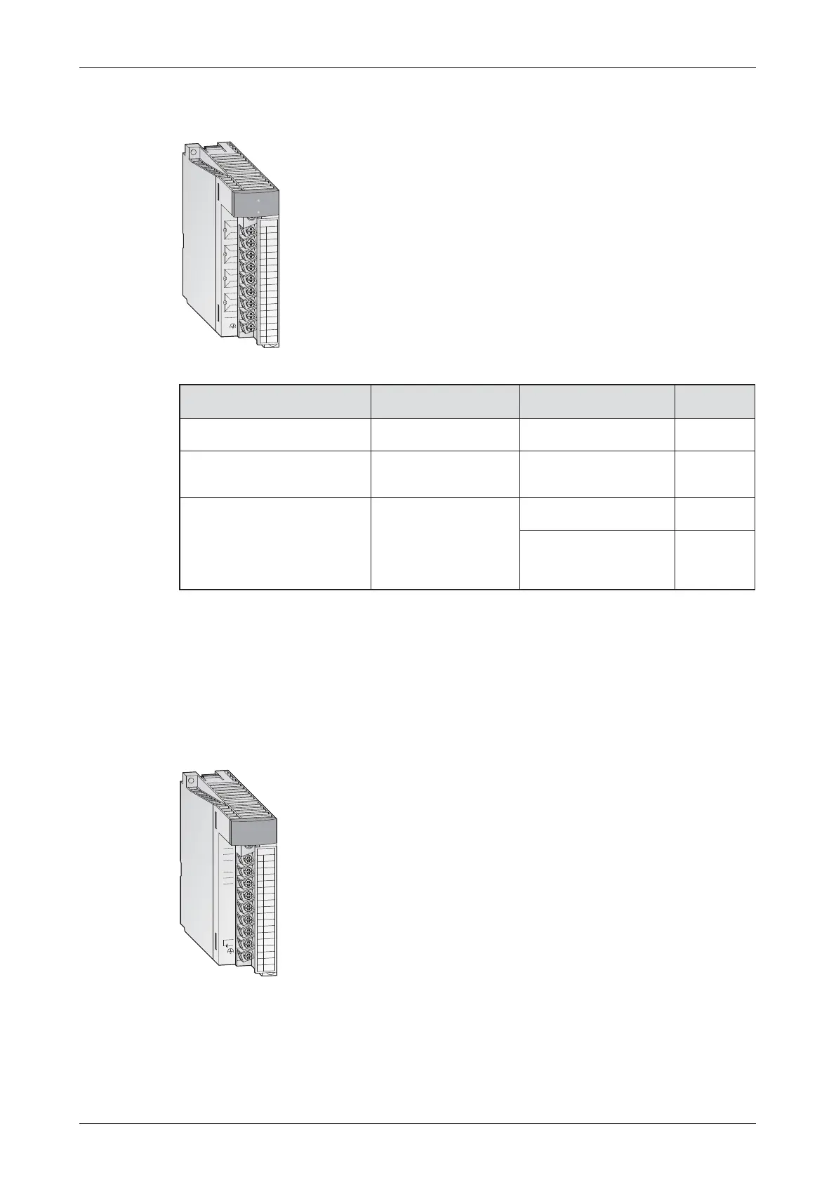
Special features
쎲
Up to 4 temperatures can be measured by one module
쎲
The disconnection of the temperature sensor can be detected on each
channel
쎲 Selection of sampling processing/time averaging processing/count
averaging processing
쎲 Error compensation by offset/gain value setting
쎲 Alarm output when limit value is exceeded
쎲 Potential isolation between process and control by means of an
opto-coupler is a standard feature. Additional potential isolation
between the channels for Q64TDV-GH and Q64RD-G.
Analog output modules
Analog output modules convert a digital value from the PLC CPU into an analog voltage or cur-
rent signal that can be used to control an external device (digital/analog conversion or D/A
conversion).
The analog output signals generated by the MELSEC System Q use the standard industrial
ranges of 0–10V and 4–20mA.
MELSEC System Q Beginners Manual 3 – 33
Special Function Modules Das MELSEC System Q
Temperature sensor
Temperature acquisition
range
Max. Resolution Module
Resistance thermometer
(Pt100, JPt100)
Pt100: -200 to 850°C,
JPt 100: -180 to 600°C
0.025 °C Q64RD
Resistance thermometer
(Pt100, JPt100, Ni100)
Pt100: -200 to 850°C,
JPt 100: -180 to 600°C,
Ni100: -60 to 180 °C
0.025 °C Q64RD-G
Thermocouples type K, E, J, T, B,
R, S or N
Depends on the thermo-
couple used
B, R, S, N: 0.3°C;
K, E, J, T: 0.1°C
Q64TD
B: 0.7°C; R, S: 0.8°C;
K, T: 0.3 °C; E,T: 0.2°C;
J: 0.1°C; N: 0.4 °C;
Voltage: 4 μV
Q64TDV-GH
3
2
1
D/A
0~±10V
0~20mA
4
5
6
7
8
9
10
11
12
13
14
15
16
17
18
C
H
1
C
H
2
I+
V+
I+
COM
COM
IN 24VDC
(FG)
RUN
V+
COM
ERROR
Q62DA
The resolution of 0.333 mV respectively 0.83 µA and the extremly short
conversion time of 80 µs per output channel are only two of the many fea-
tures of this modules. Isolation between process and control by means
of opto-couplers is also a standard feature.
All modules provide removable screw terminal blocks.
3
2
1
4
5
6
7
8
9
10
11
12
13
14
15
16
17
18
Q64RD
CH1
CH2
CH3
CH4
a1
a2
a3
a3
B1
B2
B3
B3
A1
A2
A3
A3
b1
b2
b3
b3
SLD
(FG)
Q64RD
RUN
ERR.

 Loading...


