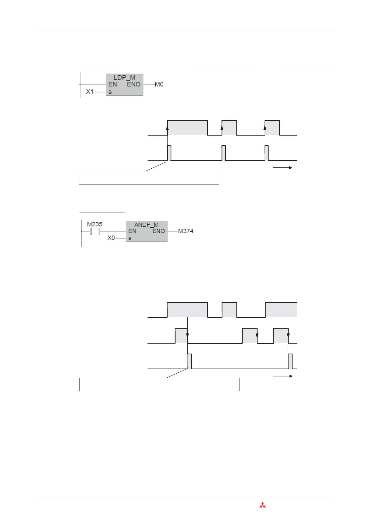
Evaluating a rising signal pulse
Evaluating a falling signal pulse
With the exception of the pulse trigger characteristic the functions of the LDP, LDF, ANDP,
ANDF, ORP and ORF instructions are identical to those of the LD, AND and OR instructions.
This means that you can use pulse-trigger operations in your programs in exactly the same
way as the conventional versions.
4–24 MITSUBISHI ELECTRIC
The Basic Instruction Set An Introduction to Programming
Ladder Diagram
IEC Instruction List
LD X1
PLS_M M0
MELSEC Instruction List
LDP X1
OUT M0
M0
X1
OFF
ON
t
(0)
(1)
0
1
Relay M0 is only switched on for the duration of a single
program cycle
Ladder Diagram
MELSEC Instruction List
LD M235
ANDF X0
OUT M374
IEC Instruction List
LD M235
ANDF_M X0
ST M374
M374
M235
t
0
1
0
1
X0
OFF
ON
(0)
(1)
If X0 is off (0) and M235 is on (1) relay M374 is switched on for the
duration of a single program cycle.

 Loading...


