1. Overview
No. 99MBA091A
1-7
・ For the halogen illuminator, plug into the connector that indicates “SURFACE”
of the illuminator (control unit). Two filters can be attached to the illuminator.
21) Transmitted illuminator (requisite selection option): Lighting device for
measurement of workpiece contour. According to your choice, either the LED
illuminator or halogen illuminator is placed.
・ For the LED illuminator, plug into the connector that indicates “CONTOUR” on
the rear panel. Two filters can be attached to the illuminator.
・ For the halogen illuminator, plug into the connector that indicates “CONTOUR”
of the illuminator (control unit). Two filters can be attached to the illuminator.
NOTE
1. For information about replacing halogen bulbs, refer to the instructions given
in "4.3.1 Replacing halogen bulbs".
2. For information about replacing LED bulbs, refer to the instructions given in
"4.3.2 Replacing LED bulbs".
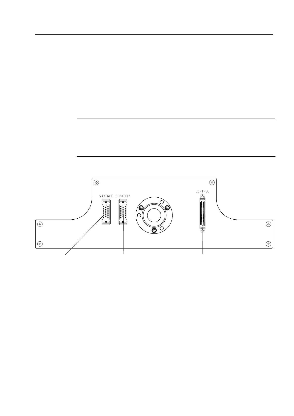
22) Rear panel: Consists of the connectors to be connected to the control unit,
transmitted illuminator, and reflected illuminator.
a) Connector for control cable
This connector is used to connect this unit and the cable connected to the control unit.
b) Connector for vertical reflected illuminator (LED)
This connector is used to connect an LED type vertical reflected illuminator. (To
connect a halogen type vertical reflected illuminator, this connector is not used.)
c) Connector for transmitted illuminator (LED)
This connector is used to connect an LED type transmitted illuminator. (To connect a
halogen type transmitted illuminator, this connector is not used.)
b) Connector for vertical reflected
illuminator (LED)
c) Connector for transmitted
illuminator (LED)
a) Connector for control cable
 Loading...