No. 99MBA091A
3-1
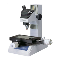
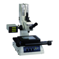
3 Measurement Setup
This chapter explains the setup for measurement including the
optical system installation and workpiece set-up.
3.1 Connection Check
Check that all connecting cables have been connected properly as specified.
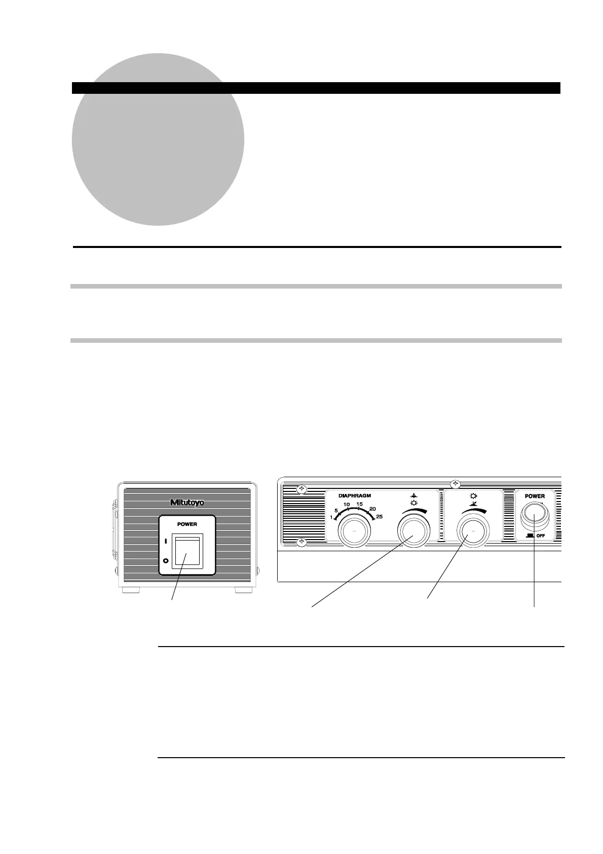
3.2 Turning the Power Supply On
Turn the power supply on according to the following procedure:
① Before turning the power switch on, turn the transmitted and vertical reflected illumination
knobs on the control panel fully counterclockwise to minimize the light intensity.
② Turn on the power switch of control unit.(Switch to ”I” position )
③ Turn the transmitted and vertical reflected illumination knobs clockwise to confirm that
both illuminators light up.
④ Turn the transmitted and vertical reflected illumination knobs clockwise to confirm that
both illuminators light up.
IMPORTANT
The counter may display error messages (E51, E52, E53) due to the procedure for
turning ON/OFF the power supply of the microscope main unit and the peripheral
equipment such as PC in the connection with some peripheral equipment when
the peripheral equipment is being connected with the counter unit at RS232C.
Be sure to perform at the following order when turning the power switch ON/OFF
・For ON ・・・・・ Peripheral equipment → Microscope main unit
・For OFF ・・・・・ Microscope main unit → Peripheral equipment
3
Control panel
Control unit
Transmitted illumination
knob
Vertical reflected illumination
knob
Auxiliary power switch
Main power switch
 Loading...