6. Specifications
No. 99MBA091A
6-7
6.7 Serial Data Output Specifications of the Counter
The measured date of the counter unit is output via the serial output connector to a peripheral,
such as two-dimensional data processing unit Micropak 9/7 or two-dimensional data
processing program QSPAK.
Communication Specifications
・ Transmission method:Half duplex
・ Transmission control:Asynchronous (Start-stop transmission)
・ Baud rate:1200bps/2400bps/4800bps/9600bps
(
※
1)
/19200bps
・ Data bit:7 bits
(
※
1)
/8 bits ASCII
・ Parity bit:Even
(
※
1)
/Odd/None
・ Stop bit:1 bit
(※
1
)
/2 bits
・ Flow control:Enabled/Disabled
(※
1
)
(※1)Default setting at the shipment
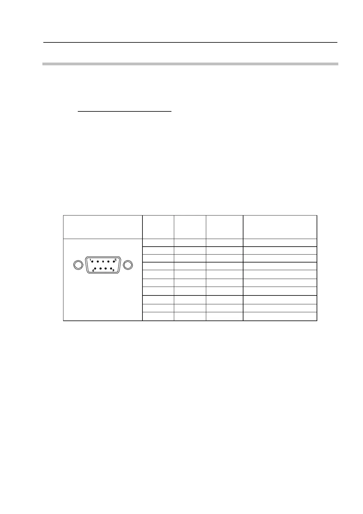
6.7.1 Connector specifications
Connector shape
Pin
number
Signal
I/O
direction
※2
Description
1
2 RD IN Accept the command
3 TD OUT Measured data
4 DTR OUT Counter is ready
5 SG
-
Signal ground
6 DSR IN Peripheral is ready
7
- -
8
- -
9
FG
- -
Frame ground
(※2)In/Out direction OUT:counter → Peripheral
The input/output circuits used are equivalent to MAX232 (MAXIM Corporation).
6.7.2 Control signal
A data request from a peripheral is accepted only if the DTR signal is “H” (space).
“H” has a +9V level.
The counter unit can transfer only if the DSR signal is “H” (space).
D-sub, 9 pins,
male, inch thread
 Loading...