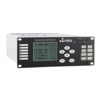
MKS 937B Operation Manual
6
List of Tables
Table 6-1 Valid gauges for autozeroing capacitance manometers of different ranges. .......................... 33
Table 6-2 Relative ionization correction factor to N2 for different gases. ................................................ 41
Table 6-3 Pin out for ion gauge remote control. ...................................................................................... 45
Table 7-1 Hot cathode connector pin out. ................................................................................................ 50
Table 7-2 Pin assignment for HC sensor type identification. ................................................................... 51
Table 7-3 Pin out for 317/345 cables. ...................................................................................................... 53
Table 7-4 Pin out of the 9 pin D-Sub connector on CM module. ............................................................. 54
Table 8-1 Pin out for the 937B relay output. ............................................................................................ 56
Table 8-2 Pin out for 937B analog output. ............................................................................................... 59
Table 8-3 Buffered analog output when sensor power is off. .................................................................... 59
Table 8-4 Buffered analog output for the cold cathode gauges (421/422/423) in N
2
. This is 2.4 higher
than the raw analog output as shown in Table 8-5. ........................................................................... 61
Table 8-5 Equations for Cold Cathode gauges (N
2
) raw analog output. .................................................. 61
Table 8-6 Buffered analog output for the 315/345 Pirani sensors. .......................................................... 64
Table 8-7 Equations for the 315/345 Pirani sensors. ................................................................................ 65
Table 8-8 Buffered analog output for the 317 Convection Pirani sensor. ................................................ 67
Table 8-9 Equations for the 317 Convection Pirani sensor. .................................................................... 68
Table 9-1 937B serial communication wiring diagram. .............................................................................. 73
Table 9-2 937B serial communication command protocol. ........................................................................ 7 3
Table 9-3 937B pressure reading commands. ........................................................................................... 74
Table 9-4 937B relay and control serial setting commands. ...................................................................... 75
Table 9-5 937B capacitance manometer serial commands. .................................................................... 76
Table 9-6 937B Pirani and Convection Pirani control commands. .......................................................... 76
Table 9-7 937B cold and hot cathode control commands. ...................................................................... 7 7
Table 9-8 937B cold and hot cathode control commands. ...................................................................... 7 8
Table 9-13 937B system commands. ...................................................................................................... 80
Table 9-14 937B serial communication error codes. ............................................................................... 80
Table 9-15 937B Profibus electrical connections. ....................................................................................... 81
Table 9-16 937B ProfiBus command list. .................................................................................................... 82
Table 9-17 937B ProfiBus output buffer map.............................................................................................. 84
Table 9-18 937B ProfiBus input buffer map. ............................................................................................... 87
Table 10-1 Description of pin assignment for adapting 937A 15 pin connector to 937B 25 pin connector
for relay output. ................................................................................................................................... 88
Table 10-2 A description of the pin assignments for adapting the 937A 25 pin connector to the 937B 37
pin connector for analog output and gauge control when a dual PR/CM board is installed in slot A. 89
Table 10-3 A description of the pin assignments for adapting the 937A 25 pin connector to the 937B 37
pin connector for analog output and gauge control when a CC board is installed in slot A. .............. 89
Table 10-4 937B serial communication wire diagram. ............................................................................... 90
Table 10-5 The 937A serial communication command protocol.............................................................. 90
Table 10-6 937A pressure reading serial commands. ............................................................................. 91
Table 10-7 The 937A relay and control setting commands. .................................................................... 9 2
Table 10-8 The 937A
cold cathode control commands. .......................................................................... 92
Table 10-9 937A user calibration commands. ......................................................................................... 93
Table 10-10 937A system commands. .................................................................................................... 93
Table 10-11 ASCII character table. .......................................................................................................... 94
Table 12-1 Resistance readings of a normal HC sensor. ...................................................................... 1 0 9
Table 12-2 Bridge resistance value for a normal 345 Pirani sensor. ..................................................... 111
Table 12-3 Resistance values for a normal 317 convection enhanced Pirani sensor. .......................... 112

 Loading...