73
11. Setting up the Receiver
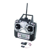
a) Receiver Connection
On its right hand side, the receiver (see figure 8, item 1) offers the option of connecting up to 6 servos with JR plug
connectors:
The receiver battery is connected either to a free slot or the top slot (BAT).
Figure 8
When connecting servos and speed controllers, always make sure of correct polarity of the plug connectors.
The impulse line of the servos (depending on manufacturer yellow, white or orange) must be connected to
the left (inner) one of the three adjacent plug-in contacts. The plug contact for the negative line (black or
brown, depending on the manufacturer) must be connected to the right (outer) pin contact.
The receiver outputs are assigned as follows:
Channel Output Helicopter Motor model plane
1 CH1 Roll servo Aileron servo
2 CH2 Pitch servo Elevator servo
3 CH3 Throttle servo Throttle servo
Flight controller Flight controller
4 CH4 Tail servo Rudder servo
5 CH5 Gyro sensitivity Additional channel 5
6 CH6 Pitch servo Additional channel 6
- BAT Battery connection* Battery connection*