09/01 AWB8230-1412GB
Selection criteria
11
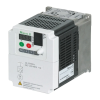
Frequency inverter characteristics
The DF5 series convert the voltage and frequency of an existing
three-phase supply to a DC voltage and use this voltage to gene-
rate a three-phase supply with adjustable voltage and frequency.
This variable three-phase supply allows stepless variability of
three-phase asynchronous motors.
a Supply via an interference suppressor
Mains voltage U
LN
(EU-rated voltage):
DF5
-322 1/3 AC 230 V, 50/60 Hz
DF5
-340 3 AC 400 V, 50/60 Hz
b The bridge rectifiers convert the AC voltage of the electrical supply to
a DC voltage.
c The DC link contains a charging resistor, smoothing capacitor and
switched-mode power supply unit. It enables coupling of the DC bus
voltage and the DC current supply:
DC bus voltage (U
ZK
) = W2 x mains voltage (U
LN
)
d IGBT power inverter:
The power inverter converts the DC voltage of the DC link to a variable
three-phase alternating voltage with variable frequency.
e Output voltage (U
2
), motor connection:
three-phase, variable AC voltage, 0 to 100 % of the input voltage
(U
LN
)
Output frequency (f
2
):
Variable frequency, 0.5 to 360 Hz
Output rated current (I
2N
):
1.8 to 22.5 A with about 1.5 times the starting current for 60 s, with
a switching frequency of 5 kHz and with an ambient temperature of
40 °C
Motor connection, assigned shaft output (P
2
):
0.18 to 2.2 kW at 230 V
0.37 to 7.5 kW at 400 V
f Programmable control section with keypad and interface.
Selection criteria
The frequency inverter is selected to suit the rated motor current.
The output rated current of the frequency inverter must however,
be greater than or equal to the rated motor current.
The following drive data is assumed to be known:
• type of motor (three-phase asynchronous motor),
• mains voltage = supply voltage of the motor (e.g. 3 ~ 400 V),
• rated motor current (guide value, dependent on the circuit type
and the supply voltage),
• load torque (quadratic, constant, with 1.5-times the starting
torque),
• ambient temperature (maximum temperature 40 °C).
The rated output current of the frequency inverter can be found in
the technical data in the Appendix from Page 107.
Figure 5: Functional diagram of the frequency inverter
a
bc d
f
e
M
3
˜
h
h
With the parallel connection of multiple motors to the
output of a frequency inverter, the motor currents are
subject to vector addition, i.e. the active in-phase current
and reactive current components are added separately.
Select the frequency inverter rating to ensure that the
total current can be supplied by the frequency inverter.
h
If a motor switches during operation on the output of a
frequency inverter, the motor draws a multiple of its rated
current. Select the rating of the frequency inverter to
ensure that the starting current plus the sum of the
currents of the running motors does not exceed the rated
output current of the frequency inverter.

 Loading...