DF5 Operation
09/01 AWB8230-1412GB
44
If a fault has occurred due to overcurrent or overvoltage, increase
the acceleration or deceleration time (a Section ”Acceleration
time 1”, Page 76 and Section ”Deceleration time 1” Page 77).
By default, the ON key and the potentiometer on the keypad
(a Fig. 39 and a Table 7) have no functions assigned to
them. For details about activating these operator controls, see
Section ”Setting the frequency and start command parameters”,
Page 78.
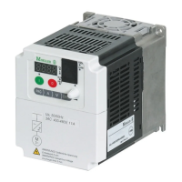
LCD keypad
The following illustration shows the LCD keypad of the DF5.
Table 7: Explanation of the operating and indication elements
Operation with LCD keypad
The functions of the DF5 are organized in parameter groups. The
following sections describe how to set the parameter values and
how the setting menu is structured.
For a detailed description of the parameters, see Section ”Setting
Parameters”, Page 75.
Menu overview
The following figure shows the sequence in which the parameters
appear on the display. Table 8 provides a brief description of the
parameters.
Caution!
Check the following points during or after the “initial
operation” so that damage to the motor does not occur:
• Was the direction of rotation correct?
• Has a fault occurred during acceleration or
deceleration?
• Was the frequency display correct?
• Did any unusual motor noises or vibrations occur?
Figure 39: Keypad view
For an explanation of the elements, see Table 7.
RUN
PRG
POWER
Hz
A
MIN
MAX
PRG
ENTER
a
k
j
i
hgf
e
d
c
b
Number Name Explanation
a RUN LED LED lights up in RUN mode, if the
frequency inverter is ready for operation
or operational.
b
7 segment
display
Display for frequency, motor current,
error messages, etc.
c
POWER LED LED is lit when the frequency inverter
has power.
d
Hz or A LED Indication in b: output frequency (Hz)
or output current (A)
e
Potentio-
meter and LED
Frequency setpoint setting
LED is lit when the potentiometer is
activated.
f
ENTER key The key is used for saving entered or
changed parameters.
g
Arrow keys Selecting functions, changing numeric
values
Increase
Reduce
h
PRG key For selecting and exiting the program-
ming mode.
i
OFF key Stop the running motor and acknow-
ledge a fault message. Active by
default, also for actuation through
terminals.
j On key and
LED
Starts the motor in the specified direc-
tion (not active by default).
k
PRG LED LED is lit during parameterization.
ENTER
PRG

 Loading...