Installation
09/01 AWB8230-1412GB
34
Parallel connection of motors on a frequency inverter
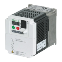
The DF5 series frequency inverters can control multiple motors
connected in parallel. If differing motor speeds are required, they
must be selected via the number of pole pairs and/or the gear
transmission ratio.
The load resistance on the output of the frequency inverter is
reduced by parallel connection of the motors. The total stator
inductivity is reduced and the leakage capacitance increases. As a
result, the current distortion is larger when compared to operation
with a single motor load. In order to reduce the current distortion,
chokes or sinusoidal filters can be used on the frequency inverter
output.
If motors with large differences in output power (e.g. 0.37 kW and
2.2 kW) are connected in parallel to the output of a frequency
inverter, problems can occur during the start phase and at low
speeds. It is possible, that motors with a low motor rating are
unable to develop the required torque. This is due to the relatively
high ohmic resistance's in the stators of these motors. They require
a higher voltage during the start phase and at low speeds.
Motor cable
Only screened motor cables may be used for EMC related compa-
tability. The length of the motor cable and the associated use of
further components has an influence on the operating mode and
the operational behaviour. With parallel operation (multiple
motors connected to the frequency inverter output) the resulting
cable lengths l
res
must be calculated:
l
res
= Sl
M
x Wn
M
Sl
M
: Sum of all motor cable lengths
n
M
: Number of motor circuits
Keep the motor cables as short as possible as it will positively
influence the drive behaviour.
Figure 28: Parallel connection of multiple motors
K1M
F1
M1
U1 V1 W1
K2M
F2
M2
U1 V1 W1
K3M
F3
M3
U1 V1 W1
M
3
˜
M
3
˜
M
3
˜
Caution!
If a frequency inverter controls a number of motors in
parallel, the contactors for the individual motors must be
designed for AC
-3 operation. You may not use the mains
contactors from the table in the Appendix Section ”Mains
contactors”, Page 113. These mains contactors are only
designed for the mains (primary) currents of the frequency
inverter. If they are used in the motor circuit, the contacts
could weld.
h
The current consumption of all the connected motors may
not exceed the rated output current I
2N
of the frequency
inverter.
h
It is not possible to use electronic motor protection when
operating the frequency inverter with a number of
connected motors. You must however, protect each motor
with Thermistors and/or overload relays.
h
With long motor cables, the leakage currents can cause
the “earth fault” fault indication due to parasitic cable
capacities. In this case, motor filters must be used.

 Loading...