M Series AC Servo
User Manual
125
Rev. 1.1
9/13/2021
400-820-9661
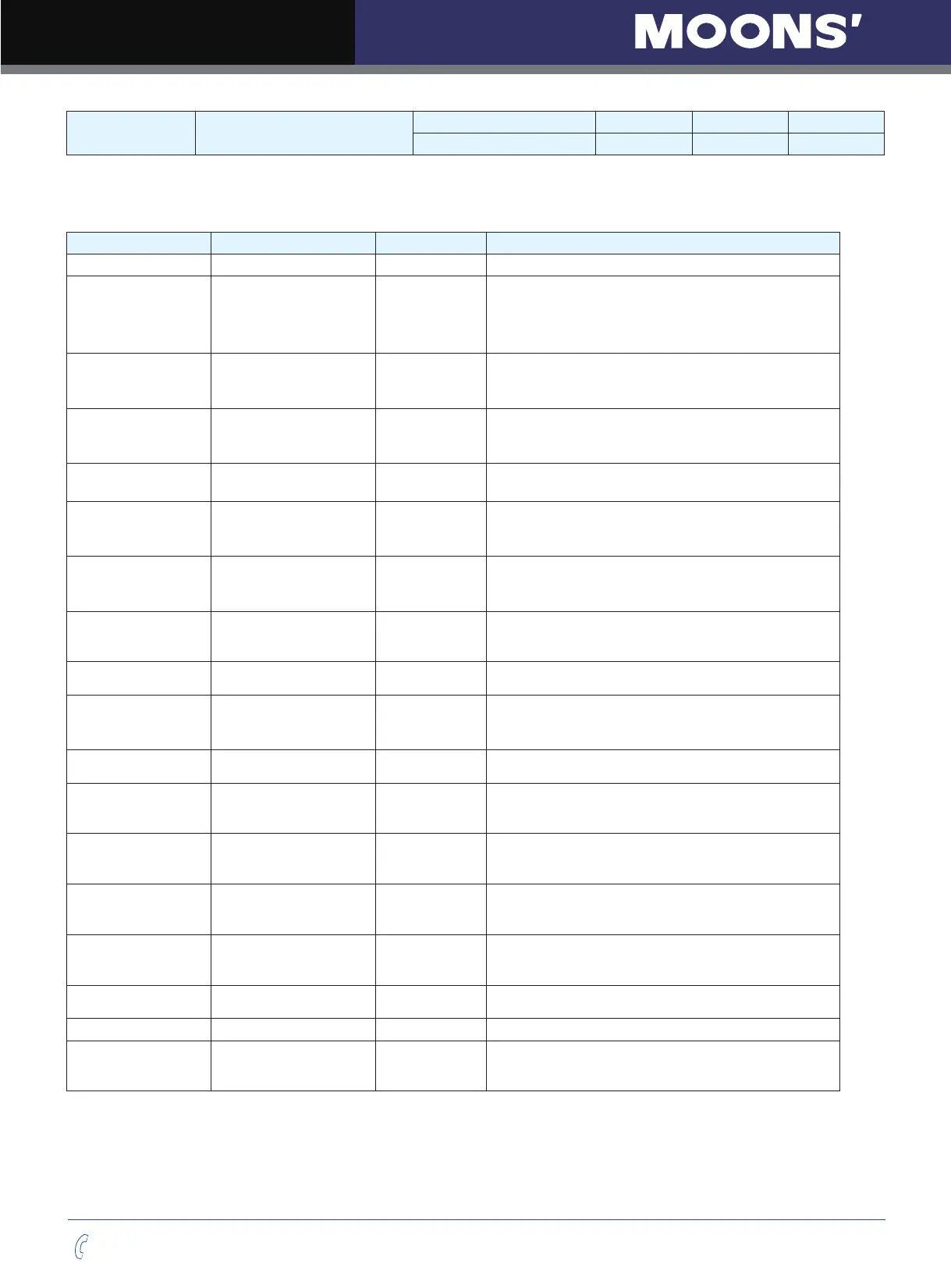
P-12 (CM) Main control mode
Data Range Default Unit Data type
1~8
,
10~18
,
21
,
22
,
25 7 ------ DEC
Parameter P-12 (CM) is used to set drive
’
s control mode.
Parameter mode list are as follows:
Mode Control Signal P-12 (CM) Description
SCL command mode SCL command 1 Use SCL command to control motor
’
s output torque
Analog input torque
mode
+10~-10V Analog signal 2
Use external analog voltage input signal to control
motor
’
s output torque.
Analog torque mode: No run/stop signal,
No direction signal.
Analog input torque
mode
+10~-10V Analog signal 3
Analog torque mode: no run/stop signal;
X2 is closed, motor will change its current rotary
direction.
Analog input torque
mode
+10~-10V Analog signal 4
Analog torque mode: no run/stop signal;
X2 is open, motor will change its current rotary
direction.
Analog input torque
mode
+10~-10V Analog signal 5
Analog torque mode: X1 for run/stop signal,
No direction signal.
Analog input torque
mode
+10~-10V Analog signal 6
Analog torque mode: X1 for run/stop signal;
X2 is open, motor will change its current rotary
direction.
Analog input torque
mode
+10~-10V Analog signal 8
Analog torque mode: X1 for run/stop signal;
X2 is close, motor will change its current rotary
direction.
Digital pulse position
mode
STEP & Direction;
CW/CCW Pulse; A/B
Quadrature.
7
Up to 500KHz open collector input signal or up to
2MHz dierential input signal.
Command velocity
mode
SCL command 10 Use SCL command to control motor rotation velocity.
Analog velocity mode +10~-10V Analog signal 11
Using external analog voltage input to motor velocity.
Analog velocity mode, NO run/stop signal, X2 is
direction switch.
Analog velocity mode +10~-10V Analog signal 12
Analog velocity mode, X1 is run/stop signal, X2 is
direction switch
Velocity mode Digitial input signal 15
Prole velocity mode, after drive is enabled. The drive
will run at velocity set by P-21 (JS). NO run/stop signal,
X2 is direction switch.
Velocity mode Digitial input signal 16
Prole velocity mode, after drive is enabled. The drive
will run at velocity set by P-21 (JS). NO run/stop signal,
X2 is direction switch.
Multi velocity mode Digitial input signal 17
Prole velocity mode, NO run/stop signal. X2 is
direction switch. X10, X11, X12 is speed selection
switch.
Multi velocity mode Digitial input signal 18
Prole velocity mode, X1 is run/stop switch. X2 is
direction switch. X10, X11, X12 is speed selection
switch.
Point to point Velocity SCL command 21
Use SCL command to control point to point position
mode.
Analog position mode +10~-10V Analog signal 22 Use analog input voltage signal for position control .
Position table Internal position mode 25
It have two motion control mode: linear motion with
maximum of 64 position set points, and rotary motion
with maximum of 32 position division points.