Radio Types and Installation Kits
21-61
3. Connect one end of the power cable (FKN8508A) to the iNET’s PWR connector and
tighten the attached screws. Connect the other end of the cable to the AUX1A connector
on the RTU’s power supply module. See Figure 21-53 and Figure 21-54 below.)
4. Connect one end of the data cable (FKN8512A) to the iNET’s COM2 connector using the
attached screws. Connect the other end of the communication cable to the ACE3600 CPU
module port configured for the radio.
5. Connect the small end of the antenna cable (FKN8511A) to the iNET’s ANT (Antenna)
connector.
Unscrew the nut and locking washer from the other end of the antenna cable.
If the RTU is inside an enclosure, thread the end of the cable through the opening on the
bottom of the enclosure and screw on the nut and locking washer from outside the
enclosure.
6. Connect the antenna cable to an external antenna.
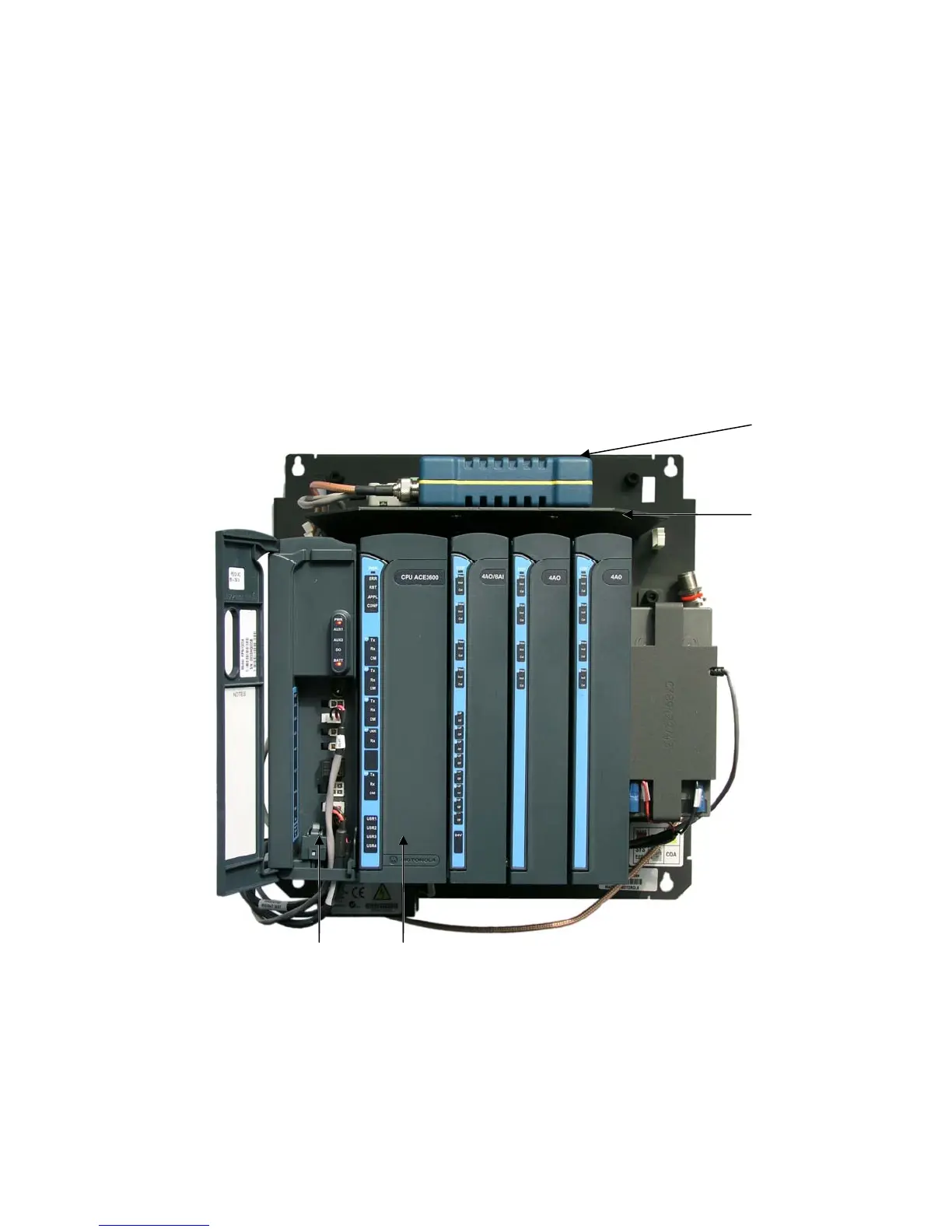
Figure 21-53 iNET 900 Radio Modem Installed on ACE3600 Chassis
Power Supply CPU
Radio
Radio
Bracket
(
FHN7067A)

 Loading...


