7-2 Schematics, Component Location Diagrams, and Parts Lists: List of Schematics, Component Location Diagrams, and Parts Lists
May 25, 2005 6881096C74-B
HUE4039A Main Board Layout—Side 2 Bottom 7-104
HUE4039A Main Board Parts List 7-105
HUE4043A Main Board Layout—Side 1 Top 7-116
HUE4043A Main Board Layout—Side 1 Bottom 7-117
HUE4043A Main Board Layout—Side 2 Top 7-118
HUE4043A Main Board Layout—Side 2 Bottom 7-119
HUE4043A Main Board Parts List 7-120
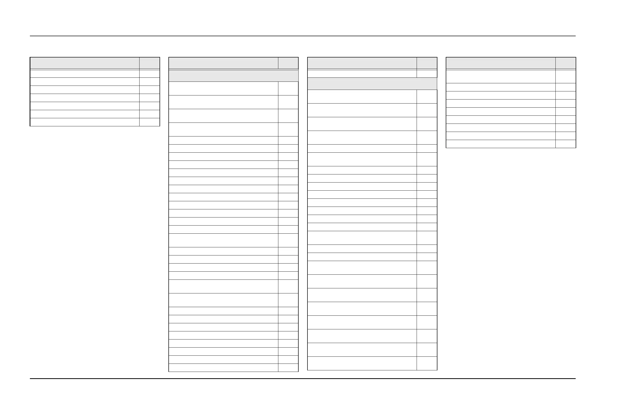
Table 7-1. List of Schematics, Component Location
Diagrams, and Parts Lists (Continued)
Figure Title Page
UHF Range 2
HUE4040A Main Board Overall Block Diagram and
Interconnections
7-132
HUE4040A Controller Block Diagram and
Interconnections (Sheet 1 of 2)
7-133
HUE4040A Controller Block Diagram and
Interconnections (Sheet 2 of 2)
7-134
HUE4040A Controller URCHIN IC, MUX, and
AD5320 DAC Schematic
7-135
HUE4040A Controller Audio Schematic 7-136
HUE4040A Controller Power Control Schematic 7-137
HUE4040A Frequency Generation Unit Schematic 7-138
HUE4040A Receive VCO Schematic 7-139
HUE4040A Transmit VCO Schematic 7-140
HUE4040A Receiver Back-End Schematic 7-141
HUE4040A Receiver Front-End Schematic 7-142
HUE4040A Receiver Mixer Schematic 7-143
HUE4040A Receiver Preselector Schematic 7-144
HUE4040A Receiver IF Schematic 7-145
HUE4040A RF Power Amplifier (RF PA) Schematic 7-146
HUE4040A Output Network (ON) Schematic 7-147
HUE4040A Secure Block Diagram and
Interconnections
7-148
HUE4040A Rear Accessory Connector Schematic 7-149
HUE4040A Power Supply Schematic 7-150
HUE4040A USB/RS232/SB9600 Schematic 7-151
HUE4040A Secure SB9600 Schematic 7-152
HUE4040A Secure Control-Head Connector
Schematic (Sheet 1 of 2)
7-153
HUE4040A Secure Control-Head Connector
Schematic (Sheet 2 of 2)
7-154
HUE4040A Secure Interface Connector Schematic 7-155
HUE4040A Secure Interface Board Schematic 7-156
HUE4040A Main Board Layout—Side 1 Top 7-157
HUE4040A Main Board Layout—Side 1 Middle 7-158
HUE4040A Main Board Layout—Side 1 Bottom 7-159
HUE4040A Main Board Layout—Side 2 Top 7-160
HUE4040A Main Board Layout—Side 2 Middle 7-161
HUE4040A Main Board Layout—Side 2 Bottom 7-162
Table 7-1. List of Schematics, Component Location
Diagrams, and Parts Lists (Continued)
Figure Title Page
HUE4040A Main Board Parts List 7-163
700-800 MHz
HUF4017A Main Board Overall Block Diagram and
Interconnections
7-174
HUF4017A Controller Block Diagram and
Interconnections (Sheet 1 of 3)
7-175
HUF4017A Controller Block Diagram and
Interconnections (Sheet 2 of 3)
7-176
HUF4017A Controller Block Diagram and
Interconnections (Sheet 3 of 3)
7-177
HUF4017A Controller Audio Schematic 7-178
HUF4017A Power, Data, Secure, and Front/Rear
Connector Block Diagrams
7-179
HUF4017A USB/RS232/SB9600 Schematic 7-180
Rear Accessory Connector (J0402) Schematic 7-181
Control-Head Front Connector Schematic 7-182
Controller Power Supply/Emergency Schematic 7-183
Controller RS232/SB9600 Schematic 7-184
Controller VIP Input/Output Schematic 7-185
Controller Secure Interface Connector Schematic 7-186
Secure Interface Board Schematic 7-187
HUF4017A Controller Urchin IC, MUX, and
AD5320 DAC Schematic
7-188
HUF4017A Controller Power Supply Schematic 7-189
HUF4017A Receiver Back-End Schematic 7-190
HUF4017A Receiver Front-End Schematic (Sheet
1 of 2)
7-191
HUF4017A Receiver Front-End Schematic (Sheet
2 of 2)
7-192
HUF4017A Receiver Intermediate Frequency (IF)
Schematic
7-193
HUF4017A RF Power Amplifier (PA) Schematic
(Sheet 1 of 2)
7-194
HUF4017A RF Power Amplifier (PA) Schematic
(Sheet 2 of 2)
7-195
HUF4017A Frequency Generation Unit Overall
Schematic (Sheet 1 of 2)
7-196
HUF4017A Frequency Generation Unit Overall
Schematic (Sheet 2 of 2)
7-197
HUF4017A Frequency Generation Unit 800 MHz
Receive Injection Schematic
7-198
Table 7-1. List of Schematics, Component Location
Diagrams, and Parts Lists (Continued)
Figure Title Page
HUF4017A Frequency Generation Unit 800 MHz
Transmit Injection Schematic
7-199
HUF4017A Main Board Layout—Side 1 Top 7-200
HUF4017A Main Board Layout—Side 1 Middle 7-201
HUF4017A Main Board Layout—Side 1 Bottom 7-202
HUF4017A Main Board Layout—Side 2 Top 7-203
HUF4017A Main Board Layout—Side 2 Middle 7-204
HUF4017A Main Board Layout—Side 2 Bottom 7-205
HUF4017A Daughtercard Module Board Layout 7-206
HUF4017A Main Board Parts List 7-207
Table 7-1. List of Schematics, Component Location
Diagrams, and Parts Lists (Continued)
Figure Title Page

 Loading...


